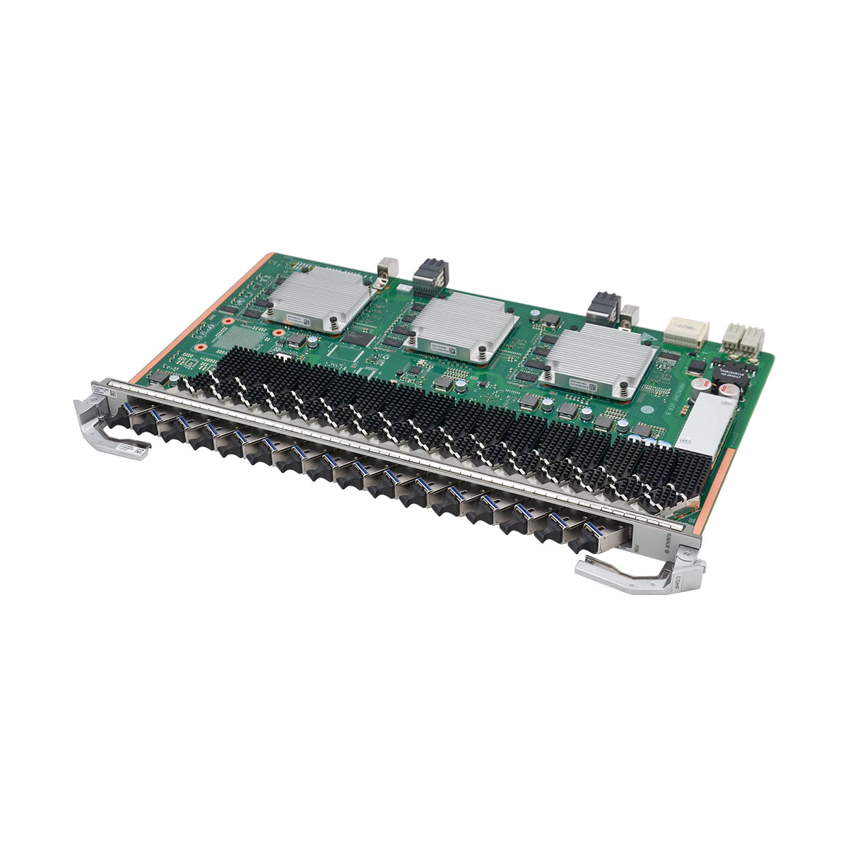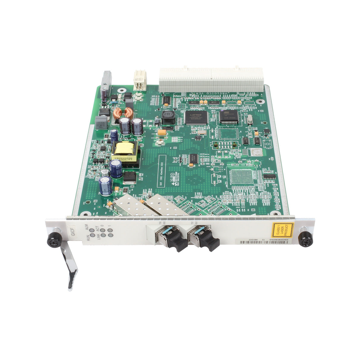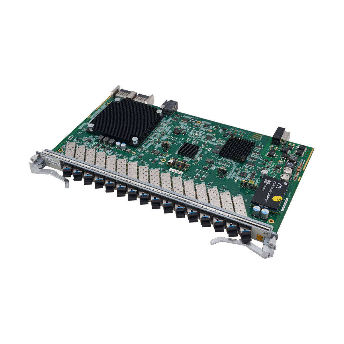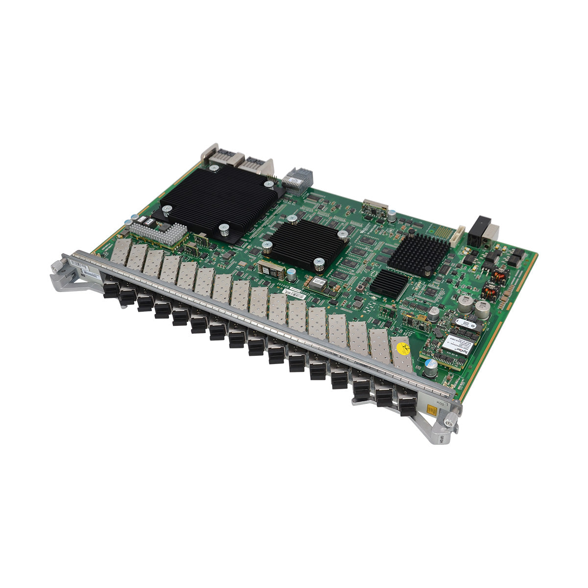




ME0D0SRUAI75 (Switch and Route Processing Unit A21(SRUA-1T-H, 32G Memory))
| Item | Details |
|---|---|
| Description | Switch and Route Processing Unit A21(SRUA-1T-H, 32G Memory) |
| Part Number | 03050HFJ |
| Model | ME0D0SRUAI75 |
| Card type | SRU |
| Silkscreen | SRUA-1T-H |
| Port | Connector Type | Description | Available Components |
|---|---|---|---|
| FSP0, FSP1 | RJ45 | Port for fast inter-chassis switchovers. Reserved. | 8-core shielded cable |
| GE/10GE | SFP/SFP+ | Reserved. | Reserved |
| HP-GE0, HP-GE1 | SFP | High-precision clock interface | Optical module (34060286/S4016067/34060484) and Atom GPS timing SFP module (03034CGQ) |
| MGMT-ETH | RJ45 | Connects to the NMS workstation. It supports half-duplex and full-duplex modes. | Super category 5 shielded twisted pair |
| CON | RJ45 | It connects to the console for on-site system configuration. The default baud rate is 9600 bit/s, and the baud rate is configurable. | 8-core shielded cable |
| AUX | RJ45 | Used to redirect to the serial port of the peer device. The default baud rate is 9600 bit/s. | 8-core shielded cable |
| CLK | RJ45 | Used to input or output 2 Mbit/s clock signals, 2 MHz clock signals. | 120-ohm clock cable. If the peer interface is an SMB interface, a 120-to-75-ohm converter is required. |
| TOD | RJ45 | Inputs or outputs 1pps+ASCII time signals or DCLS time signals. | 120-ohm clock cable. If the peer interface is an SMB interface, a 120-to-75-ohm converter is required. |
| CLK-INT | RJ45 | Inputs or outputs 2 Mbit/s clock signals, 2 MHz clock signals, 1pps+ASCII time signals, or two channels of DCLS time signals. It is reserved. | 120-ohm clock cable |
| CLK/TEST | SMA | Clock test port. | 50-ohm clock cable |
| USB | USB Type A | USB interface, reserved for future use. | - |
| Functions and Features | Description |
|---|---|
| Basic function |
1. It is responsible for system control and management, including route calculation, device management and maintenance, and device monitoring. It also functions as the system synchronization unit to provide high-precision and high-reliability synchronization clock and time signals. 2. Switches cells between BSUs/MSUs, communicates with the main control boards over Ethernet, is subject to centralized control and management of the main control boards, and monitors the board temperature and voltage. |
| Reliability and availability |
Hot swapping is supported. The system control and switching fabric functions are integrated. The system control units work in 1:1 backup mode, and the switching fabric units work in 3+1 backup mode. The four SFUs load-balance services at the same time. If one SFU is faulty or replaced, the other three SFUs automatically take over its services to prevent service interruptions. This improves system reliability. |
| Restrictions and remarks | 1. In V800R025C00SPC500 and later versions, this main control board can be used with the ME0D0SRUAI72. Different types of boards have different maximum power consumptions. After an original main control board is replaced with another type of main control board, ensure that an additional power margin of at least 20 W is available compared to the original configuration. Otherwise, a power insufficiency alarm may be generated. Other scenarios do not support mixed use of different types of main control boards. |
| Breakout supported | No |
| Interface rate auto-sensing supported | No |