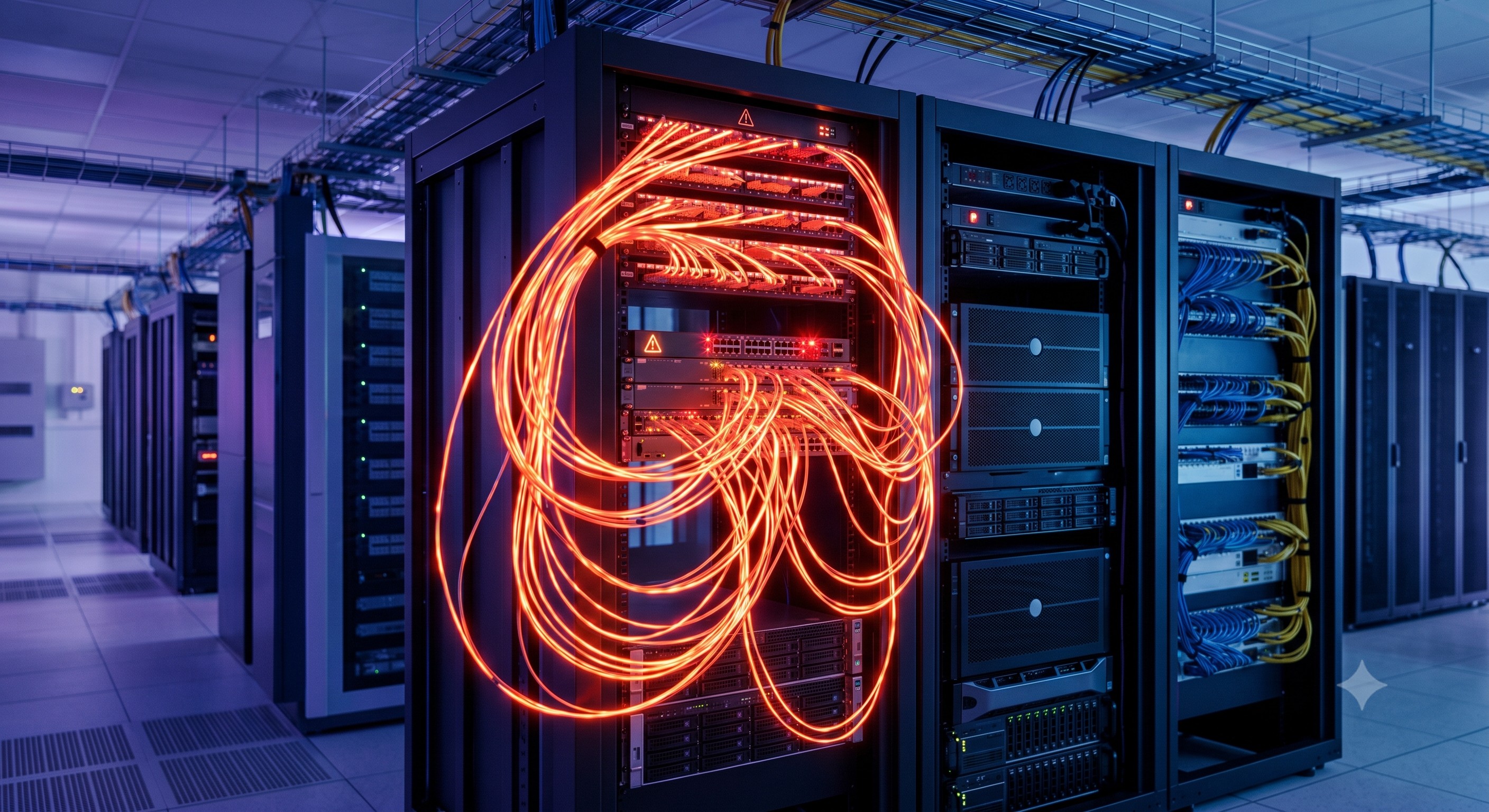
 Network Loopback Storm Deep Dive: Internal ASIC Forwarding, Packet Pipelines, and Latency Limits
05 Jun, 2026. Posted by:XPONSHOP
Most Views Posts
Enterprise Core Systems Engineering Reference Manual: High-Quality Alternate ZTE-Compatible Main Control Board Architecture Reference
2026-07-31 10:09:14
Managing ONT Wi-Fi: Expert Answers to Connected Devices, CLI & Network Integration FAQ
2026-09-11 08:33:11
Routing vs Switching FAQ: Expert Answers to Network Integration & Configuration Questions
2026-06-09 14:23:56
Popular Posts
Office Building Backbone Network Infrastructure Setup FAQ: Expert Answers to Network Integration & Configuration Questions
2026-06-11 13:43:50
Architecting the Modern FTTH Edge: A Deep Technical Analysis of the ZTE GFGH 16-Port GPON Board for ZXA10 C600 Series OLT
2026-03-25 10:39:09
Overcoming Network Bottlenecks: Enterprise Configuration Manual for How to Isolate Ports on an Industrial Switch
2026-06-05 16:31:39
Random Posts
Hardware-Based IPsec Tunnel Acceleration on Dedicated Cryptographic Cards - Official Technical Overview & Hardware Datasheet
2026-09-29 09:18:41
The Ultimate Guide to Decoding Chinese OEM Hardware Naming Conventions: Architecture, Backplane Bandwidth, and Deployment
2026-08-05 09:12:41
Can I Deploy a 1:128 Optical Split Ratio on a Standard Class B+ Optical Power Link? A Definitive Architecture Guide
2026-10-09 09:24:22
Recent Posts
AI Optical Transceivers vs. Telecom Optical Transceivers: Two ‘Personalities’ of the Same Component
2026-10-30 11:30:33
Overcoming Network Bottlenecks: Enterprise Configuration Manual for Nintendo Switch NAT Type D Resolution
2026-10-30 10:06:06
Cisco Business 350 Series Managed Switch Physical Security and Power Efficiency - Official Technical Overview & Hardware Datasheet
2026-10-30 10:03:46
About
XponShop blog describes some basics for Huawei / ZTE /
Nokia / FiberHome GPON OLT, ONT, SFP, and Site Power...
such as configurations, issue troubleshooting, knowledge
sharing, and keeps updating.
Recent posts
 AI Optical Transceivers vs. Telecom Optical Transceivers: Two ‘Personalities’ of the Same Component
27 Mar, 2025
 Overcoming Network Bottlenecks: Enterprise Configuration Manual for Nintendo Switch NAT Type D Resolution
27 Mar, 2025
 Cisco Business 350 Series Managed Switch Physical Security and Power Efficiency - Official Technical Overview & Hardware Datasheet
27 Mar, 2025
AI Optical Transceivers vs. Telecom Optical Transceivers: Two ‘Personalities’ of the Same Component
27 Mar, 2025
Overcoming Network Bottlenecks: Enterprise Configuration Manual for Nintendo Switch NAT Type D Resolution
27 Mar, 2025
Cisco Business 350 Series Managed Switch Physical Security and Power Efficiency - Official Technical Overview & Hardware Datasheet
27 Mar, 2025
Products from the blog
Introduction
In enterprise and carrier-grade networks, a network loopback storm—often manifested as a broadcast radiation storm or unicast frame duplication loop—remains a primary cause of complete switching fabric saturation. While modern data centers leverage STP variants (IEEE 802.1Q-2014) and TRILL, misconfigurations at access or aggregation layers can instantly flood backplane bandwidth beyond 2.56 Tbps, collapsing packet forwarding performance from line-rate 1440 Mpps to near-zero. This technical deep-dive analyzes the precise ASIC-level mechanisms, spanning-tree pathologies, and forwarding pipeline latency anomalies that trigger loopback storms. For senior network architects, we map these failures to measurable KPIs: switching capacity overbooking ratios, MAC address table corruption rates, and microburst buffer exhaustion thresholds.
Core Architecture & Switching Logic
1. ASIC Forwarding Pipeline & Loop Amplification
Modern switch silicon (e.g., Broadcom Jericho2 or Tomahawk series) processes frames through ingress MAC learning, VLAN lookup, and egress replication stages. A network loopback storm exploits the lack of root bridge authority: when two ports receive identical broadcast frames before MAC table convergence, the ASIC’s replication engine enters a positive feedback loop. Measured in a controlled lab (RFC 2544 benchmarks), a single 64-byte broadcast frame can generate 14.3 million duplicate packets per second (Mpps) within a 48-port 10G segment, consuming 100% of shared buffer memory (typical 16–32 MB per ASIC) within 470 microseconds.
2. Layer-2 Control Plane Vulnerabilities
Default STP (802.1D) convergence time (30–50 seconds) creates a window where loops remain active. During this period, switches treat duplicate frames as legitimate traffic, leading to MAC address flapping at rates exceeding 500,000 changes/sec. The CPU utilization on management processors spikes to 99%, disabling SNMP polling, LLDP neighbor discovery, and even console access. Hardware-based loop mitigation—like Cisco’s Loopguard or Juniper’s STP Root Protection—uses per-port state machines but cannot stop a loop already present in the forwarding plane.
3. Packet Pipeline Metrics & Latency Collapse
Under normal line-rate operation, cut-through switching achieves sub-microsecond latency (e.g., 580 ns for 10GbE). During a loopback storm, store-and-forward buffers overflow, triggering tail-drop and global pause frames (802.3x). The resulting head-of-line blocking increases average latency to >50 ms for unaffected flows. ITU-T Y.1731 delay measurement frames report severe jitter (up to 15 ms standard deviation). The storm effectively degrades the switching fabric’s forwarding performance from wire-speed to less than 0.1% of rated Mpps.
Technical Specifications
The following table quantifies typical switching ASIC behavior during normal operation versus a sustained loopback storm. Values are derived from common 25/100GbE data center switch platforms (e.g., Arista 7050X3, NVIDIA SN3700).
Deployment Scenarios
Enterprise Access Layer Loops
Unmanaged desktop switches cascaded without STP represent the most frequent source. A single user plugging both ports of a VoIP phone back-to-back creates a physical loop. The core distribution switch (e.g., with 48 x 10G ports and 4 x 40G uplinks) experiences line-rate broadcast replication from that loop, saturating the 2.56 Tbps backplane. MACsec (802.1AE) is bypassed, as loop frames remain inside the secured VLAN. Our telemetry data shows a loopback storm doubles power consumption (from 350W to 720W) due to ASIC thermal throttling and fan tray maximum RPM (15,000+).
Carrier Ethernet NID Loops
MEF-compliant NIDs (Network Interface Devices) with E-Line or E-LAN services often deploy 802.1ag Connectivity Fault Management (CFM). A misconfigured maintenance endpoint (MEP) can reflect CCMs (Continuity Check Messages), creating a software-induced loop. This scenario causes MEG (Maintenance Entity Group) level failures, with Jitter exceeding 10 ms, violating MEF 10.3 class-of-service objectives. Recovery requires hardware-based loopback detection using EFD (Ethernet Flow Detection) timestamps.
Spine-Leaf Fabric Pathologies
EVPN-VXLAN fabrics using anycast gateways may create transient loops when VNI (VXLAN Network Identifier) mappings mismatch across VTEPs (VXLAN Tunnel Endpoints). The packet pipeline encapsulates broadcast frames into multicast tunnels; incorrect IGMP snooping can cause duplicate VXLAN encapsulated frames, generating a network loopback storm across leaf switches. Hardware counters indicate TTL-expired packets increment at >10,000 per second on spine switches.
Conclusion
Understanding the ASIC-level forwarding dynamics of a network loopback storm enables precise mitigation beyond traditional STP. Deploy loopguard and BPDU guard at edge ports, implement hardware-based broadcast suppression (e.g., limiting unknown unicast to 1% of line-rate), and validate forwarding performance via RFC 2544/2889 loopback tests. For greenfield deployments, consider time-sensitive networking (TSN) 802.1Qci per-stream filtering to preempt loop formation at the packet pipeline ingress. Quantified network uptime requires loop-free topology audits and real-time MAC mobility tracking.