 Routing vs Switching - Layer 3 Platform Specification & Architectural Whitepaper
09 Jun, 2026. Posted by:XPONSHOP
Most Views Posts
Nokia OLT-to-ONT Distance Compensation and Propagation Delay Calibration Sheet - Official Technical Overview & Hardware Datasheet
2026-09-02 10:21:09
The Ultimate Guide to Replacing Broken Branded ONTs with OEM Equivalents: Architecture, Backplane Bandwidth, and Deployment
2026-08-12 13:59:02
Are 40G QSFP+ SR4 Compatible with MTP/MPO Ribbon Fiber? 8 Critical Deployment & Configuration Questions
2026-09-01 11:16:40
Popular Posts
The Ultimate Guide to Fiber to the Room (FTTR): Architecture, Backplane Bandwidth, and Deployment
2026-08-21 10:30:51
Troubleshooting optical module compatibility: SFP/SFP+ and QSFP28 integration FAQ
2026-06-23 15:43:28
Overcoming Network Bottlenecks: Enterprise Configuration Manual for Huawei OLT
2026-07-09 13:37:39
Random Posts
Troubleshooting ONT Mesh: Optical Interfaces, Stacking Errors & L3 Protocols
2026-09-07 10:23:47
Troubleshooting Core Switch Connection Drops: Optical Interfaces, Stacking Errors & L3 Protocols
2026-06-04 15:37:00
Layer 2 Broadcast Storm Suppression Configuration on Enterprise Switches - Official Technical Overview & Hardware Datasheet
2026-08-21 10:43:52
Recent Posts
AI Optical Transceivers vs. Telecom Optical Transceivers: Two ‘Personalities’ of the Same Component
2026-10-30 11:30:33
Overcoming Network Bottlenecks: Enterprise Configuration Manual for Nintendo Switch NAT Type D Resolution
2026-10-30 10:06:06
Cisco Business 350 Series Managed Switch Physical Security and Power Efficiency - Official Technical Overview & Hardware Datasheet
2026-10-30 10:03:46
About
XponShop blog describes some basics for Huawei / ZTE /
Nokia / FiberHome GPON OLT, ONT, SFP, and Site Power...
such as configurations, issue troubleshooting, knowledge
sharing, and keeps updating.
Recent posts
 AI Optical Transceivers vs. Telecom Optical Transceivers: Two ‘Personalities’ of the Same Component
27 Mar, 2025
 Overcoming Network Bottlenecks: Enterprise Configuration Manual for Nintendo Switch NAT Type D Resolution
27 Mar, 2025
 Cisco Business 350 Series Managed Switch Physical Security and Power Efficiency - Official Technical Overview & Hardware Datasheet
27 Mar, 2025
AI Optical Transceivers vs. Telecom Optical Transceivers: Two ‘Personalities’ of the Same Component
27 Mar, 2025
Overcoming Network Bottlenecks: Enterprise Configuration Manual for Nintendo Switch NAT Type D Resolution
27 Mar, 2025
Cisco Business 350 Series Managed Switch Physical Security and Power Efficiency - Official Technical Overview & Hardware Datasheet
27 Mar, 2025
Products from the blog
PRODUCT IDENTIFICATION AND EXECUTIVE OVERVIEW
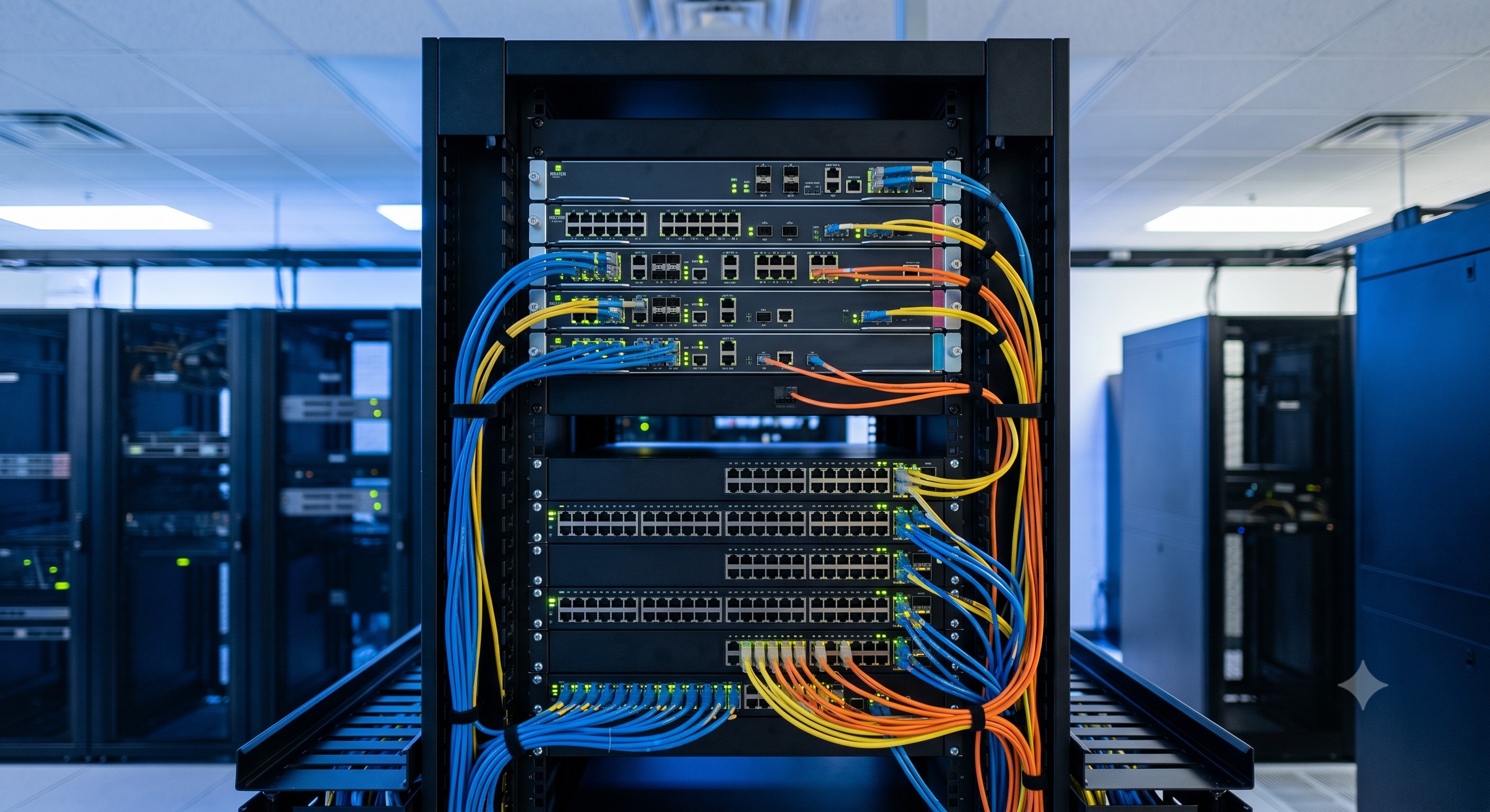
This document delineates the fundamental architectural distinctions between Layer 2 Switching and Layer 3 Routing within the context of enterprise and carrier-grade networks. The following technical overview establishes the functional separation, hardware forwarding engine logic, and deployment use-cases for each paradigm. Our platforms integrate both switching and routing capabilities within a unified chassis, enabling seamless migration between broadcast domain segmentation and IP internetworking.
CORE INTERNAL TOPOLOGY: SWITCHING FABRIC VS ROUTING ENGINE
Layer 2 Switching operates at the Data Link Layer (L2) utilizing MAC address tables for frame forwarding. Forwarding decisions are non-IP aware and rely on hardware-based Content Addressable Memory (CAM) for wire-speed frame replication. In contrast, Layer 3 Routing operates at the Network Layer (L3) utilizing IP routing tables and Forwarding Information Bases (FIB). Routing engines employ Ternary CAM (TCAM) for longest prefix match (LPM) lookups, enabling path selection across autonomous systems. The key differentiator is control plane involvement: switches forward frames based on static MAC entries, while routers exchange routing protocol updates (OSPF, BGP, IS-IS) to dynamically populate the FIB.
SWITCHING SUBSYSTEM CAPABILITIES (L2 DOMAIN)
- Non-blocking switching fabric with cut-through or store-and-forward modes
- VLAN segmentation and IEEE 802.1Q trunking
- Spanning Tree Protocol (STP/MSTP) for loop prevention
- MAC address learning and aging
- Link Aggregation Control Protocol (LACP/IEEE 802.3ad)
- IGMP snooping for multicast frame filtering
ROUTING SUBSYSTEM CAPABILITIES (L3 DOMAIN)
- Static and dynamic IP routing (OSPFv2/v3, BGP-4, IS-IS, EIGRP)
- Virtual Routing and Forwarding (VRF) instances
- Policy-based routing (PBR) leveraging ACL classification
- ECMP for load balancing across equal-cost paths
- Route redistribution and route filtering
- MPLS LDP and segment routing (SR-MPLS)
HARDWARE-LEVEL FORWARDING ENGINE DIFFERENTIATION
The platform architecture separates L2 forwarding (performed by the switching ASIC) from L3 routing (performed by the network processor or routing ASIC). Unified silicon devices blur this distinction by supporting both MAC and IP lookup tables, but the operational behavior remains distinct: switching offers microsecond latency for intra-subnet traffic, while routing introduces slightly higher, deterministic latency for inter-subnet packet manipulation (TTL decrement, IP header checksum recomputation).
OPERATIONAL ADVANTAGES FOR HYBRID DEPLOYMENTS
- Switching: Optimized for high-throughput, low-latency intra-VLAN communication
- Routing: Enables scalable internetworking, broadcast containment, and security zone segmentation
- Integrated platforms: Support L2 VPN (VPLS) and L3 VPN (MPLS/IPSec) on same hardware
- Hardware offload: Routing tables stored in TCAM to avoid CPU punting
SPECIFICATION MATRIX: SWITCHING VS ROUTING MODE
| Forwarding Decision Basis | MAC Destination Address | IP Destination Address (Longest Match) |
| Forwarding Information Base | CAM Table (VLAN + MAC) | FIB / RIB (IP Prefix + Next-Hop) |
| Lookup Algorithm | Exact Match | Longest Prefix Match (LPM) |
| Loop Prevention | Spanning Tree Protocol | TTL Expiry and Route Metric (Split Horizon) |
| Broadcast Handling | Floods within VLAN | Does not forward by default (Broadcast boundary) |
| Scalability Limit | 16K - 1M MAC addresses | 256K - 8M IPv4/IPv6 routes |
| Typical Latency (64B) | 300 ns - 2 µs | 2 µs - 15 µs |
REGULATORY COMPLIANCE AND INTEROPERABILITY STANDARDS
The routing and switching subsystems comply with IEEE 802.1, RFC 1812 (Router Requirements), and MEF carrier Ethernet specifications. All line cards and supervisor engines maintain NEBS Level 3 and ETSI environmental compliance for telco-grade deployment.
VERIFIED TOPOLOGIES: CAMPUS ACCESS (SWITCHING) VS WAN CORE (ROUTING)
- Campus access layer: Pure L2 switching with 802.1X authentication
- Distribution layer: L3 routing for inter-VLAN traffic and first-hop redundancy (HSRP/VRRP)
- Core layer: High-speed MPLS routing with segment routing and traffic engineering
ORDERING SKU DIFFERENTIATION
- SKU-SW48T: 48-port Gigabit L2 switching line card (MAC table only)
- SKU-RT24X: 24-port 10GE L3 routing line card with full BGP feature set
- SKU-HYB32Q: 32-port 40/100GE hybrid line card (concurrent L2/L3 forwarding engine)
📥 Download Technical Specification
Click the button below to view or download the full official PDF datasheet.
⬇️ Download Official PDF