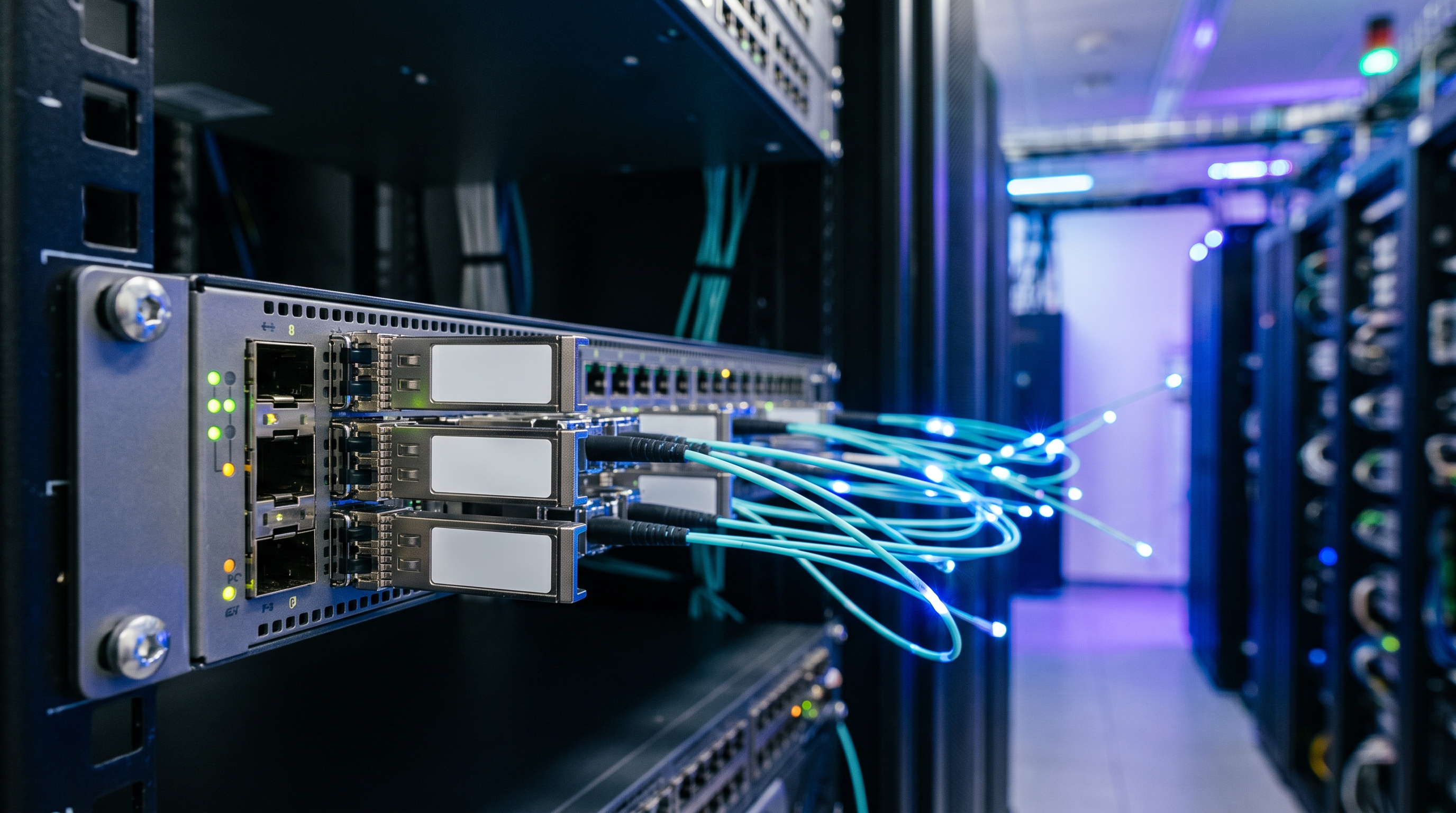
 SFP/SFP+/XFP Transceiver Labels Deep Dive: Internal ASIC Forwarding, Packet Pipelines, and Latency Limits
07 Sep, 2026. Posted by:XPONSHOP
Most Views Posts
Step Guide: How Do I Download&Activate Huawei Switch License?
2025-10-22 09:05:05
Huawei H901MPLA vs H901MPLB FAQ: Expert Answers to Network Integration & Configuration Questions
2026-07-09 13:39:13
Enterprise Core Systems Engineering Reference Manual: Digital Signage Network Distribution Matrix Switch
2026-06-17 13:53:52
Popular Posts
The Ultimate Guide to Negotiating SLA with OEM Suppliers: Architecture, Backplane Bandwidth, and Deployment
2026-08-04 10:04:06
Troubleshooting OEM GPON SFP Stick Transceivers: Optical Interfaces, Stacking Errors & L3 Protocols
2026-09-24 09:38:13
The Ultimate Guide to How Does Optical Back-Reflection (ORL) Reduce Upstream Speed on High-Split Networks?: Architecture, Backplane Bandwidth, and Deployment
2026-10-14 16:58:22
Maximizing Core Network ROI: A Total Cost of Ownership Analysis of 10GbE enterprise router price
2026-05-21 15:26:40
ZXR10 5960-52TD - Official Technical Overview & Hardware Datasheet
2026-10-14 17:12:51
Random Posts
Troubleshooting SFP Optical Interfaces: Expert Answers to Network Integration & Configuration Questions
2026-08-06 13:40:09
High-Quality Chinese OEM Dual-Mode XPON ONU Hardware Selection Matrix - Official Technical Overview & Hardware Datasheet
2026-07-03 10:33:48
Overcoming Network Bottlenecks: Enterprise Configuration Manual for how to configure VLAN trunking on core router
2026-06-05 16:50:20
Recent Posts
AI Optical Transceivers vs. Telecom Optical Transceivers: Two ‘Personalities’ of the Same Component
2026-10-30 11:30:33
Overcoming Network Bottlenecks: Enterprise Configuration Manual for Nintendo Switch NAT Type D Resolution
2026-10-30 10:06:06
Cisco Business 350 Series Managed Switch Physical Security and Power Efficiency - Official Technical Overview & Hardware Datasheet
2026-10-30 10:03:46
About
XponShop blog describes some basics for Huawei / ZTE /
Nokia / FiberHome GPON OLT, ONT, SFP, and Site Power...
such as configurations, issue troubleshooting, knowledge
sharing, and keeps updating.
Recent posts
 AI Optical Transceivers vs. Telecom Optical Transceivers: Two ‘Personalities’ of the Same Component
27 Mar, 2025
 Overcoming Network Bottlenecks: Enterprise Configuration Manual for Nintendo Switch NAT Type D Resolution
27 Mar, 2025
 Cisco Business 350 Series Managed Switch Physical Security and Power Efficiency - Official Technical Overview & Hardware Datasheet
27 Mar, 2025
AI Optical Transceivers vs. Telecom Optical Transceivers: Two ‘Personalities’ of the Same Component
27 Mar, 2025
Overcoming Network Bottlenecks: Enterprise Configuration Manual for Nintendo Switch NAT Type D Resolution
27 Mar, 2025
Cisco Business 350 Series Managed Switch Physical Security and Power Efficiency - Official Technical Overview & Hardware Datasheet
27 Mar, 2025
Products from the blog
基本
文件
流程
错误
SQL
调试
- 请求信息 : 2026-11-04 15:17:50 HTTP/2.0 GET : https://www.xponshop.com/blog/sfp-sfp-xfp-transceiver-labels-deep-dive-internal-asic-forwarding-packet-pipelines-and-latency-limits.html
- 运行时间 : 0.150432s [ 吞吐率:6.65req/s ] 内存消耗:1,344.39kb 文件加载:171
- 查询信息 : 0 queries
- 缓存信息 : 0 reads,0 writes
- 会话信息 : SESSION_ID=84b4c1249c4db79f2838fad5c565e22e
- /www/wwwroot/xpshop/public/index.php ( 2.34 KB )
- /www/wwwroot/xpshop/vendor/autoload.php ( 0.78 KB )
- /www/wwwroot/xpshop/vendor/composer/autoload_real.php ( 1.68 KB )
- /www/wwwroot/xpshop/vendor/composer/platform_check.php ( 1.04 KB )
- /www/wwwroot/xpshop/vendor/composer/ClassLoader.php ( 15.99 KB )
- /www/wwwroot/xpshop/vendor/composer/autoload_static.php ( 15.70 KB )
- /www/wwwroot/xpshop/vendor/topthink/think-helper/src/helper.php ( 8.64 KB )
- /www/wwwroot/xpshop/vendor/topthink/think-orm/stubs/load_stubs.php ( 0.17 KB )
- /www/wwwroot/xpshop/vendor/topthink/framework/src/think/Exception.php ( 1.75 KB )
- /www/wwwroot/xpshop/vendor/topthink/framework/src/think/Facade.php ( 2.81 KB )
- /www/wwwroot/xpshop/vendor/symfony/polyfill-mbstring/bootstrap.php ( 8.43 KB )
- /www/wwwroot/xpshop/vendor/symfony/polyfill-mbstring/bootstrap80.php ( 9.93 KB )
- /www/wwwroot/xpshop/vendor/symfony/deprecation-contracts/function.php ( 1.02 KB )
- /www/wwwroot/xpshop/vendor/ezyang/htmlpurifier/library/HTMLPurifier.composer.php ( 0.10 KB )
- /www/wwwroot/xpshop/vendor/hyperf/engine/src/Functions.php ( 0.87 KB )
- /www/wwwroot/xpshop/vendor/ralouphie/getallheaders/src/getallheaders.php ( 1.65 KB )
- /www/wwwroot/xpshop/vendor/symfony/polyfill-php80/bootstrap.php ( 1.54 KB )
- /www/wwwroot/xpshop/vendor/symfony/translation/Resources/functions.php ( 0.57 KB )
- /www/wwwroot/xpshop/vendor/thinkcmf/cmf/src/common.php ( 105.49 KB )
- /www/wwwroot/xpshop/vendor/yansongda/supports/src/Functions.php ( 1.59 KB )
- /www/wwwroot/xpshop/vendor/guzzlehttp/guzzle/src/functions_include.php ( 0.16 KB )
- /www/wwwroot/xpshop/vendor/guzzlehttp/guzzle/src/functions.php ( 5.72 KB )
- /www/wwwroot/xpshop/vendor/topthink/think-queue/src/common.php ( 1.04 KB )
- /www/wwwroot/xpshop/vendor/yansongda/pay/src/Functions.php ( 11.15 KB )
- /www/wwwroot/xpshop/vendor/thinkcmf/cmf/think/App.php ( 18.43 KB )
- /www/wwwroot/xpshop/vendor/topthink/framework/src/think/Container.php ( 15.93 KB )
- /www/wwwroot/xpshop/vendor/psr/container/src/ContainerInterface.php ( 1.06 KB )
- /www/wwwroot/xpshop/vendor/thinkcmf/cmf-app/src/provider.php ( 0.25 KB )
- /www/wwwroot/xpshop/vendor/thinkcmf/cmf/think/Http.php ( 7.47 KB )
- /www/wwwroot/xpshop/vendor/topthink/think-helper/src/helper/Str.php ( 7.51 KB )
- /www/wwwroot/xpshop/vendor/topthink/framework/src/think/Env.php ( 4.87 KB )
- /www/wwwroot/xpshop/app/common.php ( 3.15 KB )
- /www/wwwroot/xpshop/vendor/topthink/framework/src/helper.php ( 19.12 KB )
- /www/wwwroot/xpshop/vendor/topthink/framework/src/think/Config.php ( 4.79 KB )
- /www/wwwroot/xpshop/vendor/thinkcmf/cmf/src/config/app.php ( 1.39 KB )
- /www/wwwroot/xpshop/vendor/topthink/framework/src/think/facade/Env.php ( 1.71 KB )
- /www/wwwroot/xpshop/vendor/thinkcmf/cmf/src/config/cache.php ( 0.83 KB )
- /www/wwwroot/xpshop/vendor/thinkcmf/cmf/src/config/console.php ( 1.14 KB )
- /www/wwwroot/xpshop/vendor/thinkcmf/cmf/src/config/log.php ( 1.41 KB )
- /www/wwwroot/xpshop/vendor/thinkcmf/cmf/src/config/route.php ( 1.59 KB )
- /www/wwwroot/xpshop/vendor/thinkcmf/cmf/src/config/template.php ( 0.65 KB )
- /www/wwwroot/xpshop/vendor/thinkcmf/cmf/src/config/view.php ( 1.09 KB )
- /www/wwwroot/xpshop/config/app.php ( 0.09 KB )
- /www/wwwroot/xpshop/config/queue.php ( 1.33 KB )
- /www/wwwroot/xpshop/data/config/config.php ( 0.09 KB )
- /www/wwwroot/xpshop/data/config/database.php ( 2.40 KB )
- /www/wwwroot/xpshop/data/config/lang.php ( 0.46 KB )
- /www/wwwroot/xpshop/vendor/thinkcmf/cmf-app/src/event.php ( 0.58 KB )
- /www/wwwroot/xpshop/vendor/topthink/framework/src/think/Event.php ( 7.23 KB )
- /www/wwwroot/xpshop/app/event.php ( 0.25 KB )
- /www/wwwroot/xpshop/vendor/topthink/framework/src/think/Lang.php ( 7.49 KB )
- /www/wwwroot/xpshop/vendor/thinkcmf/cmf/src/listener/InitHookListener.php ( 2.59 KB )
- /www/wwwroot/xpshop/vendor/topthink/framework/src/think/facade/Route.php ( 4.76 KB )
- /www/wwwroot/xpshop/vendor/thinkcmf/cmf/think/Route.php ( 24.37 KB )
- /www/wwwroot/xpshop/vendor/topthink/framework/src/think/route/RuleName.php ( 5.55 KB )
- /www/wwwroot/xpshop/vendor/topthink/framework/src/think/route/Domain.php ( 5.71 KB )
- /www/wwwroot/xpshop/vendor/topthink/framework/src/think/route/RuleGroup.php ( 13.91 KB )
- /www/wwwroot/xpshop/vendor/thinkcmf/cmf/think/route/Rule.php ( 24.55 KB )
- /www/wwwroot/xpshop/vendor/topthink/framework/src/think/route/RuleItem.php ( 9.50 KB )
- /www/wwwroot/xpshop/vendor/topthink/framework/src/think/facade/Cache.php ( 2.11 KB )
- /www/wwwroot/xpshop/vendor/topthink/framework/src/think/Cache.php ( 5.11 KB )
- /www/wwwroot/xpshop/vendor/topthink/framework/src/think/Manager.php ( 4.09 KB )
- /www/wwwroot/xpshop/vendor/psr/simple-cache/src/CacheInterface.php ( 4.82 KB )
- /www/wwwroot/xpshop/vendor/topthink/think-helper/src/helper/Arr.php ( 16.72 KB )
- /www/wwwroot/xpshop/vendor/topthink/framework/src/think/cache/driver/File.php ( 7.89 KB )
- /www/wwwroot/xpshop/vendor/topthink/framework/src/think/cache/Driver.php ( 8.52 KB )
- /www/wwwroot/xpshop/vendor/topthink/framework/src/think/contract/CacheHandlerInterface.php ( 2.06 KB )
- /www/wwwroot/xpshop/vendor/topthink/framework/src/think/facade/Event.php ( 1.83 KB )
- /www/wwwroot/xpshop/app/listener/InitHookListener.php ( 0.82 KB )
- /www/wwwroot/xpshop/app/portal/route.php ( 7.83 KB )
- /www/wwwroot/xpshop/vendor/topthink/framework/src/think/Request.php ( 56.59 KB )
- /www/wwwroot/xpshop/vendor/topthink/think-orm/src/facade/Db.php ( 0.96 KB )
- /www/wwwroot/xpshop/vendor/topthink/framework/src/think/Db.php ( 2.99 KB )
- /www/wwwroot/xpshop/vendor/topthink/think-orm/src/DbManager.php ( 8.72 KB )
- /www/wwwroot/xpshop/vendor/topthink/framework/src/think/Log.php ( 6.51 KB )
- /www/wwwroot/xpshop/vendor/psr/log/src/LoggerTrait.php ( 2.79 KB )
- /www/wwwroot/xpshop/vendor/psr/log/src/LoggerInterface.php ( 2.80 KB )
- /www/wwwroot/xpshop/vendor/topthink/think-orm/src/db/connector/Mysql.php ( 4.50 KB )
- /www/wwwroot/xpshop/vendor/topthink/think-orm/src/db/PDOConnection.php ( 53.54 KB )
- /www/wwwroot/xpshop/vendor/topthink/think-orm/src/db/Connection.php ( 9.19 KB )
- /www/wwwroot/xpshop/vendor/topthink/think-orm/src/db/ConnectionInterface.php ( 5.08 KB )
- /www/wwwroot/xpshop/vendor/topthink/think-orm/src/db/builder/Mysql.php ( 17.07 KB )
- /www/wwwroot/xpshop/vendor/topthink/think-orm/src/db/Builder.php ( 23.03 KB )
- /www/wwwroot/xpshop/vendor/topthink/think-orm/src/db/BaseBuilder.php ( 28.23 KB )
- /www/wwwroot/xpshop/vendor/topthink/think-orm/src/db/Query.php ( 14.82 KB )
- /www/wwwroot/xpshop/vendor/topthink/think-orm/src/db/BaseQuery.php ( 42.79 KB )
- /www/wwwroot/xpshop/vendor/topthink/think-orm/src/db/concern/TimeFieldQuery.php ( 7.65 KB )
- /www/wwwroot/xpshop/vendor/topthink/think-orm/src/db/concern/AggregateQuery.php ( 3.39 KB )
- /www/wwwroot/xpshop/vendor/topthink/think-orm/src/db/concern/ModelRelationQuery.php ( 19.62 KB )
- /www/wwwroot/xpshop/vendor/topthink/think-orm/src/db/concern/ParamsBind.php ( 3.80 KB )
- /www/wwwroot/xpshop/vendor/topthink/think-orm/src/db/concern/ResultOperation.php ( 6.90 KB )
- /www/wwwroot/xpshop/vendor/topthink/think-orm/src/db/concern/Transaction.php ( 2.90 KB )
- /www/wwwroot/xpshop/vendor/topthink/think-orm/src/db/concern/WhereQuery.php ( 18.40 KB )
- /www/wwwroot/xpshop/vendor/topthink/think-orm/src/db/concern/JoinAndViewQuery.php ( 7.23 KB )
- /www/wwwroot/xpshop/vendor/topthink/think-orm/src/db/concern/TableFieldInfo.php ( 2.56 KB )
- /www/wwwroot/xpshop/vendor/topthink/framework/src/think/log/driver/File.php ( 6.38 KB )
- /www/wwwroot/xpshop/vendor/topthink/framework/src/think/contract/LogHandlerInterface.php ( 0.89 KB )
- /www/wwwroot/xpshop/vendor/topthink/framework/src/think/log/Channel.php ( 4.04 KB )
- /www/wwwroot/xpshop/vendor/topthink/framework/src/think/event/LogRecord.php ( 0.89 KB )
- /www/wwwroot/xpshop/vendor/topthink/framework/src/think/initializer/Error.php ( 3.38 KB )
- /www/wwwroot/xpshop/vendor/topthink/framework/src/think/initializer/RegisterService.php ( 1.37 KB )
- /www/wwwroot/xpshop/vendor/services.php ( 0.25 KB )
- /www/wwwroot/xpshop/vendor/topthink/framework/src/think/service/PaginatorService.php ( 1.57 KB )
- /www/wwwroot/xpshop/vendor/topthink/framework/src/think/Service.php ( 1.70 KB )
- /www/wwwroot/xpshop/vendor/topthink/framework/src/think/service/ValidateService.php ( 1.02 KB )
- /www/wwwroot/xpshop/vendor/topthink/framework/src/think/service/ModelService.php ( 1.80 KB )
- /www/wwwroot/xpshop/vendor/thinkcmf/cmf-appstore/src/AppStoreService.php ( 1.12 KB )
- /www/wwwroot/xpshop/vendor/topthink/think-queue/src/queue/Service.php ( 1.29 KB )
- /www/wwwroot/xpshop/vendor/topthink/think-trace/src/Service.php ( 0.79 KB )
- /www/wwwroot/xpshop/vendor/topthink/framework/src/think/Middleware.php ( 6.89 KB )
- /www/wwwroot/xpshop/vendor/xia/migration/src/Service.php ( 2.02 KB )
- /www/wwwroot/xpshop/vendor/topthink/framework/src/think/initializer/BootService.php ( 0.79 KB )
- /www/wwwroot/xpshop/vendor/topthink/think-orm/src/Paginator.php ( 12.21 KB )
- /www/wwwroot/xpshop/vendor/topthink/framework/src/think/Validate.php ( 48.38 KB )
- /www/wwwroot/xpshop/vendor/topthink/think-orm/src/Model.php ( 27.82 KB )
- /www/wwwroot/xpshop/vendor/topthink/think-orm/src/model/concern/Attribute.php ( 19.62 KB )
- /www/wwwroot/xpshop/vendor/topthink/think-orm/src/model/concern/RelationShip.php ( 27.32 KB )
- /www/wwwroot/xpshop/vendor/topthink/think-orm/src/model/concern/ModelEvent.php ( 2.33 KB )
- /www/wwwroot/xpshop/vendor/topthink/think-orm/src/model/concern/TimeStamp.php ( 5.92 KB )
- /www/wwwroot/xpshop/vendor/topthink/think-orm/src/model/concern/AutoWriteId.php ( 1.50 KB )
- /www/wwwroot/xpshop/vendor/topthink/think-orm/src/model/concern/Conversion.php ( 11.25 KB )
- /www/wwwroot/xpshop/vendor/topthink/think-helper/src/contract/Arrayable.php ( 0.10 KB )
- /www/wwwroot/xpshop/vendor/topthink/think-helper/src/contract/Jsonable.php ( 0.14 KB )
- /www/wwwroot/xpshop/vendor/thinkcmf/cmf/think/Console.php ( 23.46 KB )
- /www/wwwroot/xpshop/vendor/thinkcmf/cmf-app/src/middleware.php ( 0.26 KB )
- /www/wwwroot/xpshop/vendor/topthink/framework/src/think/Pipeline.php ( 2.71 KB )
- /www/wwwroot/xpshop/vendor/topthink/think-trace/src/TraceDebug.php ( 3.05 KB )
- /www/wwwroot/xpshop/vendor/thinkcmf/cmf/src/middleware/LangDetect.php ( 5.94 KB )
- /www/wwwroot/xpshop/vendor/topthink/framework/src/think/Cookie.php ( 6.19 KB )
- /www/wwwroot/xpshop/vendor/topthink/framework/src/think/middleware/SessionInit.php ( 2.01 KB )
- /www/wwwroot/xpshop/vendor/topthink/framework/src/think/Session.php ( 1.86 KB )
- /www/wwwroot/xpshop/vendor/topthink/framework/src/think/session/driver/File.php ( 6.52 KB )
- /www/wwwroot/xpshop/vendor/topthink/framework/src/think/contract/SessionHandlerInterface.php ( 0.89 KB )
- /www/wwwroot/xpshop/vendor/topthink/framework/src/think/session/Store.php ( 7.37 KB )
- /www/wwwroot/xpshop/data/route/route.php ( 10.75 KB )
- /www/wwwroot/xpshop/vendor/thinkcmf/cmf/think/route/dispatch/Controller.php ( 7.73 KB )
- /www/wwwroot/xpshop/vendor/topthink/framework/src/think/route/Dispatch.php ( 6.29 KB )
- /www/wwwroot/xpshop/vendor/thinkcmf/cmf/src/listener/ModuleInitListener.php ( 2.20 KB )
- /www/wwwroot/xpshop/vendor/topthink/think-helper/src/Collection.php ( 17.14 KB )
- /www/wwwroot/xpshop/app/portal/controller/BlogController.php ( 5.17 KB )
- /www/wwwroot/xpshop/vendor/thinkcmf/cmf/src/controller/HomeBaseController.php ( 13.79 KB )
- /www/wwwroot/xpshop/vendor/thinkcmf/cmf/src/controller/BaseController.php ( 10.69 KB )
- /www/wwwroot/xpshop/vendor/thinkcmf/cmf/think/View.php ( 5.21 KB )
- /www/wwwroot/xpshop/vendor/topthink/framework/src/think/facade/Config.php ( 1.41 KB )
- /www/wwwroot/xpshop/vendor/topthink/framework/src/think/facade/Cookie.php ( 1.52 KB )
- /www/wwwroot/xpshop/vendor/thinkcmf/cmf/think/view/driver/Think.php ( 8.67 KB )
- /www/wwwroot/xpshop/vendor/thinkcmf/cmf/think/Template.php ( 55.14 KB )
- /www/wwwroot/xpshop/vendor/thinkcmf/cmf/think/template/driver/File.php ( 2.42 KB )
- /www/wwwroot/xpshop/vendor/thinkcmf/cmf-app/src/admin/model/LinkModel.php ( 0.92 KB )
- /www/wwwroot/xpshop/vendor/topthink/think-orm/src/model/Collection.php ( 6.93 KB )
- /www/wwwroot/xpshop/api/portal/model/SocialModel.php ( 2.51 KB )
- /www/wwwroot/xpshop/vendor/thinkcmf/cmf/src/listener/HomeLangListener.php ( 3.40 KB )
- /www/wwwroot/xpshop/vendor/topthink/framework/src/think/facade/Session.php ( 1.84 KB )
- /www/wwwroot/xpshop/app/listener/HomeInitListener.php ( 3.09 KB )
- /www/wwwroot/xpshop/api/portal/model/NewsModel.php ( 1.73 KB )
- /www/wwwroot/xpshop/vendor/thinkcmf/cmf/src/lib/Storage.php ( 4.40 KB )
- /www/wwwroot/xpshop/vendor/thinkcmf/cmf/src/lib/storage/Local.php ( 2.97 KB )
- /www/wwwroot/xpshop/api/portal/model/PortalPostModel.php ( 26.71 KB )
- /www/wwwroot/xpshop/vendor/topthink/think-orm/src/db/Raw.php ( 1.28 KB )
- /www/wwwroot/xpshop/vendor/thinkcmf/cmf-app/src/admin/model/ThemeModel.php ( 12.56 KB )
- /www/wwwroot/xpshop/vendor/thinkcmf/cmf-app/src/admin/model/ThemeFileModel.php ( 1.96 KB )
- /www/wwwroot/xpshop/data/runtime/temp/english_6df7f0f34cddea77df5aa1fa9591dd7b.php ( 62.29 KB )
- /www/wwwroot/xpshop/vendor/thinkcmf/cmf-app/src/admin/model/NavMenuModel.php ( 9.60 KB )
- /www/wwwroot/xpshop/vendor/thinkcmf/cmf-extend/src/tree/Tree.php ( 10.30 KB )
- /www/wwwroot/xpshop/vendor/thinkcmf/cmf-app/src/admin/model/RouteModel.php ( 8.92 KB )
- /www/wwwroot/xpshop/app/portal/url.php ( 1.60 KB )
- /www/wwwroot/xpshop/vendor/thinkcmf/cmf-app/src/user/url.php ( 1.01 KB )
- /www/wwwroot/xpshop/vendor/thinkcmf/cmf/think/route/Url.php ( 17.14 KB )
- /www/wwwroot/xpshop/vendor/topthink/framework/src/think/Response.php ( 9.05 KB )
- /www/wwwroot/xpshop/vendor/topthink/framework/src/think/response/Html.php ( 1.01 KB )
- /www/wwwroot/xpshop/vendor/topthink/think-trace/src/Html.php ( 4.49 KB )
- CONNECT:[ UseTime:0.000259s ] mysql:host=127.0.0.1;port=3306;dbname=xpshop;charset=utf8mb4
- SHOW FULL COLUMNS FROM `cmf_news` [ RunTime:0.000975s ]
- SELECT * FROM `cmf_news` WHERE `news_status` = 1 AND `slug` = 'sfp-sfp-xfp-transceiver-labels-deep-dive-internal-asic-forwarding-packet-pipelines-and-latency-limits' LIMIT 1 [ RunTime:0.002653s ]
- SHOW FULL COLUMNS FROM `cmf_link` [ RunTime:0.000828s ]
- SELECT * FROM `cmf_link` WHERE `status` = 1 [ RunTime:0.000190s ]
- SHOW FULL COLUMNS FROM `cmf_social` [ RunTime:0.000756s ]
- SELECT * FROM `cmf_social` WHERE `status` = 1 [ RunTime:0.000184s ]
- SHOW FULL COLUMNS FROM `cmf_portal_category` [ RunTime:0.000804s ]
- SELECT * FROM `cmf_portal_category` WHERE `module_id` = 2 ORDER BY `list_order` ASC [ RunTime:0.000327s ]
- SHOW FULL COLUMNS FROM `cmf_countries` [ RunTime:0.000651s ]
- SELECT * FROM `cmf_countries` [ RunTime:0.000232s ]
- SELECT * FROM `cmf_news` WHERE `slug` = 'sfp-sfp-xfp-transceiver-labels-deep-dive-internal-asic-forwarding-packet-pipelines-and-latency-limits' LIMIT 1 [ RunTime:0.002421s ]
- SHOW FULL COLUMNS FROM `cmf_option` [ RunTime:0.000755s ]
- SELECT `option_value` FROM `cmf_option` WHERE `option_name` = 'storage' LIMIT 1 [ RunTime:0.000140s ]
- SELECT * FROM `cmf_news` WHERE `news_status` = 1 ORDER BY `create_time` DESC LIMIT 3 [ RunTime:0.003101s ]
- SHOW FULL COLUMNS FROM `cmf_portal_post` [ RunTime:0.001103s ]
- SELECT * FROM `cmf_portal_post` WHERE 0 = 1 AND `post_type` = 1 [ RunTime:0.000203s ]
- SHOW FULL COLUMNS FROM `cmf_news_comment` [ RunTime:0.000664s ]
- SELECT * FROM `cmf_news_comment` WHERE `news_id` = 896 AND `status` = 1 ORDER BY `create_time` ASC [ RunTime:0.000163s ]
- SELECT * FROM `cmf_news` ORDER BY RAND() LIMIT 5 [ RunTime:0.006381s ]
- SELECT * FROM `cmf_news` ORDER BY RAND() LIMIT 5 [ RunTime:0.005806s ]
- SELECT * FROM `cmf_news` ORDER BY RAND() LIMIT 5 [ RunTime:0.005219s ]
- SELECT * FROM `cmf_news` ORDER BY `create_time` DESC LIMIT 5 [ RunTime:0.003090s ]
- SHOW FULL COLUMNS FROM `cmf_theme_file` [ RunTime:0.000852s ]
- SELECT * FROM `cmf_theme_file` WHERE `theme` = 'default' AND `file` = 'portal/404' LIMIT 1 [ RunTime:0.000206s ]
- UPDATE `cmf_theme_file` SET `theme` = 'default' , `action` = 'portal/Index/Notfound' , `file` = 'portal/404' , `name` = '首页' , `more` = '{\"widgets_blocks\":{\"top\":{\"title\":\"\\u9876\\u90e8\",\"widgets\":{\"top_nav_202206300003\":{\"title\":\"\\u9876\\u90e8\\u5bfc\\u822a\",\"name\":\"nav\",\"display\":\"1\",\"public_widget_id\":\"top_nav\",\"version\":\"1.0.0\",\"action\":\"\",\"vars\":{\"company_name\":\"ThinkCMF\",\"nav_id\":\"\"}}}},\"body\":{\"title\":\"\\u4e3b\\u4f53\",\"widgets\":{\"home_slider_202206300003\":{\"title\":\"\\u9996\\u9875\\u5e7b\\u706f\\u7247\",\"name\":\"slider\",\"display\":\"1\",\"version\":\"1.0.0\",\"action\":\"\",\"vars\":{\"slide_id\":\"\",\"fullscreen\":1}},\"home_features_202206300003\":{\"title\":\"\\u4ea7\\u54c1\\u7279\\u6027\",\"name\":\"features\",\"display\":\"1\",\"version\":\"1.0.0\",\"action\":\"\",\"vars\":{\"sub_title\":\"Quickly understand the ThinkCMF\",\"features\":[{\"title\":\"MVC\\u5206\\u5c42\\u6a21\\u5f0f\",\"icon\":\"bars\",\"content\":\"\\u4f7f\\u7528MVC\\u5e94\\u7528\\u7a0b\\u5e8f\\u88ab\\u5206\\u6210\\u4e09\\u4e2a\\u6838\\u5fc3\\u90e8\\u4ef6\\uff1a\\u6a21\\u578b\\uff08M\\uff09\\u3001\\u89c6\\u56fe\\uff08V\\uff09\\u3001\\u63a7\\u5236\\u5668\\uff08C\\uff09\\uff0c\\u4ed6\\u4e0d\\u662f\\u4e00\\u4e2a\\u65b0\\u7684\\u6982\\u5ff5\\uff0c\\u53ea\\u662fThinkCMF\\u5c06\\u5176\\u53d1\\u6325\\u5230\\u4e86\\u6781\\u81f4\\u3002\"},{\"title\":\"\\u7528\\u6237\\u7ba1\\u7406\",\"icon\":\"group\",\"content\":\"ThinkCMF\\u5185\\u7f6e\\u4e86\\u7075\\u6d3b\\u7684\\u7528\\u6237\\u7ba1\\u7406\\u65b9\\u5f0f\\uff0c\\u5e76\\u53ef\\u76f4\\u63a5\\u4e0e\\u7b2c\\u4e09\\u65b9\\u7ad9\\u70b9\\u8fdb\\u884c\\u4e92\\u8054\\u4e92\\u901a\\uff0c\\u5982\\u679c\\u4f60\\u613f\\u610f\\u751a\\u81f3\\u53ef\\u4ee5\\u5bf9\\u5355\\u4e2a\\u7528\\u6237\\u6216\\u7fa4\\u4f53\\u7528\\u6237\\u7684\\u884c\\u4e3a\\u8fdb\\u884c\\u8bb0\\u5f55\\u53ca\\u5206\\u4eab\\uff0c\\u4e3a\\u60a8\\u7684\\u8fd0\\u8425\\u51b3\\u7b56\\u63d0\\u4f9b\\u6709\\u6548\\u53c2\\u8003\\u6570\\u636e\\u3002\"},{\"title\":\"\\u4e91\\u7aef\\u90e8\\u7f72\",\"icon\":\"cloud\",\"content\":\"\\u901a\\u8fc7\\u9a71\\u52a8\\u7684\\u65b9\\u5f0f\\u53ef\\u4ee5\\u8f7b\\u677e\\u652f\\u6301\\u4e91\\u5e73\\u53f0\\u7684\\u90e8\\u7f72\\uff0c\\u8ba9\\u4f60\\u7684\\u7f51\\u7ad9\\u65e0\\u7f1d\\u8fc1\\u79fb\\uff0c\\u5185\\u7f6e\\u5df2\\u7ecf\\u652f\\u6301SAE\\u3001BAE\\uff0c\\u6b63\\u5f0f\\u7248\\u5c06\\u5bf9\\u4e91\\u7aef\\u90e8\\u7f72\\u8fdb\\u884c\\u8fdb\\u4e00\\u6b65\\u4f18\\u5316\\u3002\"},{\"title\":\"\\u5b89\\u5168\\u7b56\\u7565\",\"icon\":\"heart\",\"content\":\"\\u63d0\\u4f9b\\u7684\\u7a33\\u5065\\u7684\\u5b89\\u5168\\u7b56\\u7565\\uff0c\\u5305\\u62ec\\u5907\\u4efd\\u6062\\u590d\\uff0c\\u5bb9\\u9519\\uff0c\\u9632\\u6cbb\\u6076\\u610f\\u653b\\u51fb\\u767b\\u9646\\uff0c\\u7f51\\u9875\\u9632\\u7be1\\u6539\\u7b49\\u591a\\u9879\\u5b89\\u5168\\u7ba1\\u7406\\u529f\\u80fd\\uff0c\\u4fdd\\u8bc1\\u7cfb\\u7edf\\u5b89\\u5168\\uff0c\\u53ef\\u9760\\uff0c\\u7a33\\u5b9a\\u7684\\u8fd0\\u884c\\u3002\"},{\"title\":\"\\u5e94\\u7528\\u6a21\\u5757\\u5316\",\"icon\":\"cubes\",\"content\":\"\\u63d0\\u51fa\\u5168\\u65b0\\u7684\\u5e94\\u7528\\u6a21\\u5f0f\\u8fdb\\u884c\\u6269\\u5c55\\uff0c\\u4e0d\\u7ba1\\u662f\\u4f60\\u5f00\\u53d1\\u4e00\\u4e2a\\u5c0f\\u529f\\u80fd\\u8fd8\\u662f\\u4e00\\u4e2a\\u5168\\u65b0\\u7684\\u7ad9\\u70b9\\uff0c\\u5728ThinkCMF\\u4e2d\\u4f60\\u53ea\\u662f\\u589e\\u52a0\\u4e86\\u4e00\\u4e2aAPP\\uff0c\\u6bcf\\u4e2a\\u72ec\\u7acb\\u8fd0\\u884c\\u4e92\\u4e0d\\u5f71\\u54cd\\uff0c\\u4fbf\\u4e8e\\u7075\\u6d3b\\u6269\\u5c55\\u548c\\u4e8c\\u6b21\\u5f00\\u53d1\\u3002\"},{\"title\":\"\\u514d\\u8d39\\u5f00\\u6e90\",\"icon\":\"certificate\",\"content\":\"\\u4ee3\\u7801\\u9075\\u5faaApache2\\u5f00\\u6e90\\u534f\\u8bae\\uff0c\\u514d\\u8d39\\u4f7f\\u7528\\uff0c\\u5bf9\\u5546\\u4e1a\\u7528\\u6237\\u4e5f\\u65e0\\u4efb\\u4f55\\u9650\\u5236\\u3002\"}]}},\"home_last_news_202206300003\":{\"title\":\"\\u6700\\u65b0\\u8d44\\u8baf\",\"name\":\"last_news\",\"display\":\"1\",\"version\":\"1.0.0\",\"action\":\"\",\"vars\":{\"last_news_category_id\":\"\"}},\"home_last_news_202206300004\":{\"title\":\"\\u6700\\u65b0\\u8d44\\u8baf\",\"name\":\"last_news\",\"display\":\"1\",\"version\":\"1.0.0\",\"action\":\"\",\"vars\":{\"last_news_category_id\":\"\"}}}},\"footer\":{\"title\":\"\\u5e95\\u90e8\",\"widgets\":{\"home_footer_202206300003\":{\"title\":\"\\u5e95\\u90e8\",\"name\":\"footer\",\"display\":\"1\",\"public_widget_id\":\"footer\",\"version\":\"1.0.0\",\"action\":\"\",\"vars\":{\"company_name\":\"ThinkCMF\",\"nav_id\":\"2\"}}}}}}' , `config_more` = '{\"widgets_blocks\":{\"top\":{\"title\":\"\\u9876\\u90e8\",\"widgets\":{\"top_nav_202206300003\":{\"title\":\"\\u9876\\u90e8\\u5bfc\\u822a\",\"name\":\"nav\",\"display\":\"1\",\"public_widget_id\":\"top_nav\"}}},\"body\":{\"title\":\"\\u4e3b\\u4f53\",\"widgets\":{\"home_slider_202206300003\":{\"title\":\"\\u9996\\u9875\\u5e7b\\u706f\\u7247\",\"name\":\"slider\",\"display\":\"1\"},\"home_features_202206300003\":{\"title\":\"\\u4ea7\\u54c1\\u7279\\u6027\",\"name\":\"features\",\"display\":\"1\"},\"home_last_news_202206300003\":{\"title\":\"\\u6700\\u65b0\\u8d44\\u8baf\",\"name\":\"last_news\",\"display\":\"1\"},\"home_last_news_202206300004\":{\"title\":\"\\u6700\\u65b0\\u8d44\\u8baf\",\"name\":\"last_news\",\"display\":\"1\"}}},\"footer\":{\"title\":\"\\u5e95\\u90e8\",\"widgets\":{\"home_footer_202206300003\":{\"title\":\"\\u5e95\\u90e8\",\"name\":\"footer\",\"display\":\"1\",\"public_widget_id\":\"footer\"}}}}}' , `description` = '首页模板文件' , `is_public` = 0 , `list_order` = '5' WHERE `theme` = 'default' AND `file` = 'portal/404' [ RunTime:0.004871s ]
- SELECT * FROM `cmf_theme_file` WHERE `theme` = 'default' AND `file` = 'portal/about' LIMIT 1 [ RunTime:0.000189s ]
- UPDATE `cmf_theme_file` SET `theme` = 'default' , `action` = 'portal/Index/index' , `file` = 'portal/about' , `name` = '首页' , `more` = '{\"widgets_blocks\":{\"top\":{\"title\":\"\\u9876\\u90e8\",\"widgets\":{\"top_nav_202206300003\":{\"title\":\"\\u9876\\u90e8\\u5bfc\\u822a\",\"name\":\"nav\",\"display\":\"1\",\"public_widget_id\":\"top_nav\",\"version\":\"1.0.0\",\"action\":\"\",\"vars\":{\"company_name\":\"ThinkCMF\",\"nav_id\":\"\"}}}},\"body\":{\"title\":\"\\u4e3b\\u4f53\",\"widgets\":{\"home_slider_202206300003\":{\"title\":\"home\",\"name\":\"slider\",\"display\":\"1\",\"vars\":{\"slide_id\":\"23\",\"fullscreen\":1}},\"home_features_202206300003\":{\"title\":\"\\u4ea7\\u54c1\\u7279\\u6027\",\"name\":\"features\",\"display\":\"1\",\"version\":\"1.0.0\",\"action\":\"\",\"vars\":{\"sub_title\":\"Quickly understand the ThinkCMF\",\"features\":[{\"title\":\"MVC\\u5206\\u5c42\\u6a21\\u5f0f\",\"icon\":\"bars\",\"content\":\"\\u4f7f\\u7528MVC\\u5e94\\u7528\\u7a0b\\u5e8f\\u88ab\\u5206\\u6210\\u4e09\\u4e2a\\u6838\\u5fc3\\u90e8\\u4ef6\\uff1a\\u6a21\\u578b\\uff08M\\uff09\\u3001\\u89c6\\u56fe\\uff08V\\uff09\\u3001\\u63a7\\u5236\\u5668\\uff08C\\uff09\\uff0c\\u4ed6\\u4e0d\\u662f\\u4e00\\u4e2a\\u65b0\\u7684\\u6982\\u5ff5\\uff0c\\u53ea\\u662fThinkCMF\\u5c06\\u5176\\u53d1\\u6325\\u5230\\u4e86\\u6781\\u81f4\\u3002\"},{\"title\":\"\\u7528\\u6237\\u7ba1\\u7406\",\"icon\":\"group\",\"content\":\"ThinkCMF\\u5185\\u7f6e\\u4e86\\u7075\\u6d3b\\u7684\\u7528\\u6237\\u7ba1\\u7406\\u65b9\\u5f0f\\uff0c\\u5e76\\u53ef\\u76f4\\u63a5\\u4e0e\\u7b2c\\u4e09\\u65b9\\u7ad9\\u70b9\\u8fdb\\u884c\\u4e92\\u8054\\u4e92\\u901a\\uff0c\\u5982\\u679c\\u4f60\\u613f\\u610f\\u751a\\u81f3\\u53ef\\u4ee5\\u5bf9\\u5355\\u4e2a\\u7528\\u6237\\u6216\\u7fa4\\u4f53\\u7528\\u6237\\u7684\\u884c\\u4e3a\\u8fdb\\u884c\\u8bb0\\u5f55\\u53ca\\u5206\\u4eab\\uff0c\\u4e3a\\u60a8\\u7684\\u8fd0\\u8425\\u51b3\\u7b56\\u63d0\\u4f9b\\u6709\\u6548\\u53c2\\u8003\\u6570\\u636e\\u3002\"},{\"title\":\"\\u4e91\\u7aef\\u90e8\\u7f72\",\"icon\":\"cloud\",\"content\":\"\\u901a\\u8fc7\\u9a71\\u52a8\\u7684\\u65b9\\u5f0f\\u53ef\\u4ee5\\u8f7b\\u677e\\u652f\\u6301\\u4e91\\u5e73\\u53f0\\u7684\\u90e8\\u7f72\\uff0c\\u8ba9\\u4f60\\u7684\\u7f51\\u7ad9\\u65e0\\u7f1d\\u8fc1\\u79fb\\uff0c\\u5185\\u7f6e\\u5df2\\u7ecf\\u652f\\u6301SAE\\u3001BAE\\uff0c\\u6b63\\u5f0f\\u7248\\u5c06\\u5bf9\\u4e91\\u7aef\\u90e8\\u7f72\\u8fdb\\u884c\\u8fdb\\u4e00\\u6b65\\u4f18\\u5316\\u3002\"},{\"title\":\"\\u5b89\\u5168\\u7b56\\u7565\",\"icon\":\"heart\",\"content\":\"\\u63d0\\u4f9b\\u7684\\u7a33\\u5065\\u7684\\u5b89\\u5168\\u7b56\\u7565\\uff0c\\u5305\\u62ec\\u5907\\u4efd\\u6062\\u590d\\uff0c\\u5bb9\\u9519\\uff0c\\u9632\\u6cbb\\u6076\\u610f\\u653b\\u51fb\\u767b\\u9646\\uff0c\\u7f51\\u9875\\u9632\\u7be1\\u6539\\u7b49\\u591a\\u9879\\u5b89\\u5168\\u7ba1\\u7406\\u529f\\u80fd\\uff0c\\u4fdd\\u8bc1\\u7cfb\\u7edf\\u5b89\\u5168\\uff0c\\u53ef\\u9760\\uff0c\\u7a33\\u5b9a\\u7684\\u8fd0\\u884c\\u3002\"},{\"title\":\"\\u5e94\\u7528\\u6a21\\u5757\\u5316\",\"icon\":\"cubes\",\"content\":\"\\u63d0\\u51fa\\u5168\\u65b0\\u7684\\u5e94\\u7528\\u6a21\\u5f0f\\u8fdb\\u884c\\u6269\\u5c55\\uff0c\\u4e0d\\u7ba1\\u662f\\u4f60\\u5f00\\u53d1\\u4e00\\u4e2a\\u5c0f\\u529f\\u80fd\\u8fd8\\u662f\\u4e00\\u4e2a\\u5168\\u65b0\\u7684\\u7ad9\\u70b9\\uff0c\\u5728ThinkCMF\\u4e2d\\u4f60\\u53ea\\u662f\\u589e\\u52a0\\u4e86\\u4e00\\u4e2aAPP\\uff0c\\u6bcf\\u4e2a\\u72ec\\u7acb\\u8fd0\\u884c\\u4e92\\u4e0d\\u5f71\\u54cd\\uff0c\\u4fbf\\u4e8e\\u7075\\u6d3b\\u6269\\u5c55\\u548c\\u4e8c\\u6b21\\u5f00\\u53d1\\u3002\"},{\"title\":\"\\u514d\\u8d39\\u5f00\\u6e90\",\"icon\":\"certificate\",\"content\":\"\\u4ee3\\u7801\\u9075\\u5faaApache2\\u5f00\\u6e90\\u534f\\u8bae\\uff0c\\u514d\\u8d39\\u4f7f\\u7528\\uff0c\\u5bf9\\u5546\\u4e1a\\u7528\\u6237\\u4e5f\\u65e0\\u4efb\\u4f55\\u9650\\u5236\\u3002\"}]}},\"home_last_news_202206300003\":{\"title\":\"\\u6700\\u65b0\\u8d44\\u8baf\",\"name\":\"last_news\",\"display\":\"1\",\"version\":\"1.0.0\",\"action\":\"\",\"vars\":{\"last_news_category_id\":\"\"}},\"home_last_news_202206300004\":{\"title\":\"\\u6700\\u65b0\\u8d44\\u8baf\",\"name\":\"last_news\",\"display\":\"1\",\"version\":\"1.0.0\",\"action\":\"\",\"vars\":{\"last_news_category_id\":\"\"}}}},\"footer\":{\"title\":\"\\u5e95\\u90e8\",\"widgets\":{\"home_footer_202206300003\":{\"title\":\"\\u5e95\\u90e8\",\"name\":\"footer\",\"display\":\"1\",\"public_widget_id\":\"footer\",\"version\":\"1.0.0\",\"action\":\"\",\"vars\":[]}}}}}' , `config_more` = '{\"widgets_blocks\":{\"top\":{\"title\":\"\\u9876\\u90e8\",\"widgets\":{\"top_nav_202206300003\":{\"title\":\"\\u9876\\u90e8\\u5bfc\\u822a\",\"name\":\"nav\",\"display\":\"1\",\"public_widget_id\":\"top_nav\"}}},\"body\":{\"title\":\"\\u4e3b\\u4f53\",\"widgets\":{\"home_slider_202206300003\":{\"title\":\"\\u9996\\u9875\\u5e7b\\u706f\\u7247\",\"name\":\"slider\",\"display\":\"1\"},\"home_features_202206300003\":{\"title\":\"\\u4ea7\\u54c1\\u7279\\u6027\",\"name\":\"features\",\"display\":\"1\"},\"home_last_news_202206300003\":{\"title\":\"\\u6700\\u65b0\\u8d44\\u8baf\",\"name\":\"last_news\",\"display\":\"1\"},\"home_last_news_202206300004\":{\"title\":\"\\u6700\\u65b0\\u8d44\\u8baf\",\"name\":\"last_news\",\"display\":\"1\"}}},\"footer\":{\"title\":\"\\u5e95\\u90e8\",\"widgets\":{\"home_footer_202206300003\":{\"title\":\"\\u5e95\\u90e8\",\"name\":\"footer\",\"display\":\"1\",\"public_widget_id\":\"footer\"}}}}}' , `description` = '首页模板文件' , `is_public` = 0 , `list_order` = '5' WHERE `theme` = 'default' AND `file` = 'portal/about' [ RunTime:0.005041s ]
- SELECT * FROM `cmf_theme_file` WHERE `theme` = 'default' AND `file` = 'portal/article' LIMIT 1 [ RunTime:0.000203s ]
- UPDATE `cmf_theme_file` SET `theme` = 'default' , `action` = 'portal/Article/index' , `file` = 'portal/article' , `name` = '文章页' , `more` = '{\"widgets_blocks\":{\"top\":{\"title\":\"\\u9876\\u90e8\",\"widgets\":{\"top_nav_202206300003\":{\"title\":\"\\u9876\\u90e8\\u5bfc\\u822a\",\"name\":\"nav\",\"display\":\"1\",\"public_widget_id\":\"top_nav\",\"version\":\"1.0.0\",\"action\":\"\",\"vars\":{\"company_name\":\"ThinkCMF\",\"nav_id\":\"\"}}}},\"body_left\":{\"title\":\"\\u4e3b\\u4f53\\u5de6\",\"widgets\":{\"article_202206300003\":{\"title\":\"\\u6587\\u7ae0\\u5185\\u5bb9\",\"name\":\"article\",\"display\":\"1\",\"version\":\"1.0.0\",\"action\":\"portal\\/Article\\/index\",\"vars\":[]},\"article_last_news_202206300003\":{\"title\":\"\\u6700\\u65b0\\u8d44\\u8baf\",\"name\":\"last_news\",\"display\":\"1\",\"version\":\"1.0.0\",\"action\":\"\",\"vars\":{\"last_news_category_id\":\"\"}}}},\"body_right\":{\"title\":\"\\u4e3b\\u4f53\\u53f3\",\"widgets\":{\"article_side_hot_articles_202206300004\":{\"title\":\"\\u70ed\\u95e8\\u6587\\u7ae0\",\"name\":\"side_hot_articles\",\"display\":\"1\",\"version\":\"1.0.0\",\"action\":\"\",\"vars\":{\"hottest_articles_category_id\":\"\"}},\"article_side_last_articles_202206300004\":{\"title\":\"\\u6700\\u65b0\\u6587\\u7ae0\",\"name\":\"side_last_articles\",\"display\":\"1\",\"version\":\"1.0.0\",\"action\":\"\",\"vars\":{\"last_articles_category_id\":\"\"}}}},\"footer\":{\"title\":\"\\u5e95\\u90e8\",\"widgets\":{\"footer_202206300003\":{\"title\":\"\\u5e95\\u90e8\",\"name\":\"footer\",\"display\":\"1\",\"public_widget_id\":\"footer\",\"version\":\"1.0.0\",\"action\":\"\",\"vars\":[]}}}}}' , `config_more` = '{\"widgets_blocks\":{\"top\":{\"title\":\"\\u9876\\u90e8\",\"widgets\":{\"top_nav_202206300003\":{\"title\":\"\\u9876\\u90e8\\u5bfc\\u822a\",\"name\":\"nav\",\"display\":\"1\",\"public_widget_id\":\"top_nav\"}}},\"body_left\":{\"title\":\"\\u4e3b\\u4f53\\u5de6\",\"widgets\":{\"article_202206300003\":{\"title\":\"\\u6587\\u7ae0\\u5185\\u5bb9\",\"name\":\"article\",\"display\":\"1\"},\"article_last_news_202206300003\":{\"title\":\"\\u6700\\u65b0\\u8d44\\u8baf\",\"name\":\"last_news\",\"display\":\"1\"}}},\"body_right\":{\"title\":\"\\u4e3b\\u4f53\\u53f3\",\"widgets\":{\"article_side_hot_articles_202206300004\":{\"title\":\"\\u70ed\\u95e8\\u6587\\u7ae0\",\"name\":\"side_hot_articles\",\"display\":\"1\"},\"article_side_last_articles_202206300004\":{\"title\":\"\\u6700\\u65b0\\u6587\\u7ae0\",\"name\":\"side_last_articles\",\"display\":\"1\"}}},\"footer\":{\"title\":\"\\u5e95\\u90e8\",\"widgets\":{\"footer_202206300003\":{\"title\":\"\\u5e95\\u90e8\",\"name\":\"footer\",\"display\":\"1\",\"public_widget_id\":\"footer\"}}}}}' , `description` = '文章页模板文件' , `is_public` = 0 , `list_order` = '10' WHERE `theme` = 'default' AND `file` = 'portal/article' [ RunTime:0.005702s ]
- SELECT * FROM `cmf_theme_file` WHERE `theme` = 'default' AND `file` = 'portal/blog' LIMIT 1 [ RunTime:0.000220s ]
- UPDATE `cmf_theme_file` SET `theme` = 'default' , `action` = 'portal/Index/index' , `file` = 'portal/blog' , `name` = '首页' , `more` = '{\"widgets_blocks\":{\"top\":{\"title\":\"\\u9876\\u90e8\",\"widgets\":{\"top_nav_202206300003\":{\"title\":\"\\u9876\\u90e8\\u5bfc\\u822a\",\"name\":\"nav\",\"display\":\"1\",\"public_widget_id\":\"top_nav\",\"version\":\"1.0.0\",\"action\":\"\",\"vars\":{\"company_name\":\"ThinkCMF\",\"nav_id\":\"\"}}}},\"body\":{\"title\":\"\\u4e3b\\u4f53\",\"widgets\":{\"home_slider_202206300003\":{\"title\":\"\\u9996\\u9875\\u5e7b\\u706f\\u7247\",\"name\":\"slider\",\"display\":\"1\",\"version\":\"1.0.0\",\"action\":\"\",\"vars\":{\"slide_id\":\"\",\"fullscreen\":1}},\"home_features_202206300003\":{\"title\":\"\\u4ea7\\u54c1\\u7279\\u6027\",\"name\":\"features\",\"display\":\"1\",\"version\":\"1.0.0\",\"action\":\"\",\"vars\":{\"sub_title\":\"Quickly understand the ThinkCMF\",\"features\":[{\"title\":\"MVC\\u5206\\u5c42\\u6a21\\u5f0f\",\"icon\":\"bars\",\"content\":\"\\u4f7f\\u7528MVC\\u5e94\\u7528\\u7a0b\\u5e8f\\u88ab\\u5206\\u6210\\u4e09\\u4e2a\\u6838\\u5fc3\\u90e8\\u4ef6\\uff1a\\u6a21\\u578b\\uff08M\\uff09\\u3001\\u89c6\\u56fe\\uff08V\\uff09\\u3001\\u63a7\\u5236\\u5668\\uff08C\\uff09\\uff0c\\u4ed6\\u4e0d\\u662f\\u4e00\\u4e2a\\u65b0\\u7684\\u6982\\u5ff5\\uff0c\\u53ea\\u662fThinkCMF\\u5c06\\u5176\\u53d1\\u6325\\u5230\\u4e86\\u6781\\u81f4\\u3002\"},{\"title\":\"\\u7528\\u6237\\u7ba1\\u7406\",\"icon\":\"group\",\"content\":\"ThinkCMF\\u5185\\u7f6e\\u4e86\\u7075\\u6d3b\\u7684\\u7528\\u6237\\u7ba1\\u7406\\u65b9\\u5f0f\\uff0c\\u5e76\\u53ef\\u76f4\\u63a5\\u4e0e\\u7b2c\\u4e09\\u65b9\\u7ad9\\u70b9\\u8fdb\\u884c\\u4e92\\u8054\\u4e92\\u901a\\uff0c\\u5982\\u679c\\u4f60\\u613f\\u610f\\u751a\\u81f3\\u53ef\\u4ee5\\u5bf9\\u5355\\u4e2a\\u7528\\u6237\\u6216\\u7fa4\\u4f53\\u7528\\u6237\\u7684\\u884c\\u4e3a\\u8fdb\\u884c\\u8bb0\\u5f55\\u53ca\\u5206\\u4eab\\uff0c\\u4e3a\\u60a8\\u7684\\u8fd0\\u8425\\u51b3\\u7b56\\u63d0\\u4f9b\\u6709\\u6548\\u53c2\\u8003\\u6570\\u636e\\u3002\"},{\"title\":\"\\u4e91\\u7aef\\u90e8\\u7f72\",\"icon\":\"cloud\",\"content\":\"\\u901a\\u8fc7\\u9a71\\u52a8\\u7684\\u65b9\\u5f0f\\u53ef\\u4ee5\\u8f7b\\u677e\\u652f\\u6301\\u4e91\\u5e73\\u53f0\\u7684\\u90e8\\u7f72\\uff0c\\u8ba9\\u4f60\\u7684\\u7f51\\u7ad9\\u65e0\\u7f1d\\u8fc1\\u79fb\\uff0c\\u5185\\u7f6e\\u5df2\\u7ecf\\u652f\\u6301SAE\\u3001BAE\\uff0c\\u6b63\\u5f0f\\u7248\\u5c06\\u5bf9\\u4e91\\u7aef\\u90e8\\u7f72\\u8fdb\\u884c\\u8fdb\\u4e00\\u6b65\\u4f18\\u5316\\u3002\"},{\"title\":\"\\u5b89\\u5168\\u7b56\\u7565\",\"icon\":\"heart\",\"content\":\"\\u63d0\\u4f9b\\u7684\\u7a33\\u5065\\u7684\\u5b89\\u5168\\u7b56\\u7565\\uff0c\\u5305\\u62ec\\u5907\\u4efd\\u6062\\u590d\\uff0c\\u5bb9\\u9519\\uff0c\\u9632\\u6cbb\\u6076\\u610f\\u653b\\u51fb\\u767b\\u9646\\uff0c\\u7f51\\u9875\\u9632\\u7be1\\u6539\\u7b49\\u591a\\u9879\\u5b89\\u5168\\u7ba1\\u7406\\u529f\\u80fd\\uff0c\\u4fdd\\u8bc1\\u7cfb\\u7edf\\u5b89\\u5168\\uff0c\\u53ef\\u9760\\uff0c\\u7a33\\u5b9a\\u7684\\u8fd0\\u884c\\u3002\"},{\"title\":\"\\u5e94\\u7528\\u6a21\\u5757\\u5316\",\"icon\":\"cubes\",\"content\":\"\\u63d0\\u51fa\\u5168\\u65b0\\u7684\\u5e94\\u7528\\u6a21\\u5f0f\\u8fdb\\u884c\\u6269\\u5c55\\uff0c\\u4e0d\\u7ba1\\u662f\\u4f60\\u5f00\\u53d1\\u4e00\\u4e2a\\u5c0f\\u529f\\u80fd\\u8fd8\\u662f\\u4e00\\u4e2a\\u5168\\u65b0\\u7684\\u7ad9\\u70b9\\uff0c\\u5728ThinkCMF\\u4e2d\\u4f60\\u53ea\\u662f\\u589e\\u52a0\\u4e86\\u4e00\\u4e2aAPP\\uff0c\\u6bcf\\u4e2a\\u72ec\\u7acb\\u8fd0\\u884c\\u4e92\\u4e0d\\u5f71\\u54cd\\uff0c\\u4fbf\\u4e8e\\u7075\\u6d3b\\u6269\\u5c55\\u548c\\u4e8c\\u6b21\\u5f00\\u53d1\\u3002\"},{\"title\":\"\\u514d\\u8d39\\u5f00\\u6e90\",\"icon\":\"certificate\",\"content\":\"\\u4ee3\\u7801\\u9075\\u5faaApache2\\u5f00\\u6e90\\u534f\\u8bae\\uff0c\\u514d\\u8d39\\u4f7f\\u7528\\uff0c\\u5bf9\\u5546\\u4e1a\\u7528\\u6237\\u4e5f\\u65e0\\u4efb\\u4f55\\u9650\\u5236\\u3002\"}]}},\"home_last_news_202206300003\":{\"title\":\"\\u6700\\u65b0\\u8d44\\u8baf\",\"name\":\"last_news\",\"display\":\"1\",\"version\":\"1.0.0\",\"action\":\"\",\"vars\":{\"last_news_category_id\":\"\"}},\"home_last_news_202206300004\":{\"title\":\"\\u6700\\u65b0\\u8d44\\u8baf\",\"name\":\"last_news\",\"display\":\"1\",\"version\":\"1.0.0\",\"action\":\"\",\"vars\":{\"last_news_category_id\":\"\"}}}},\"footer\":{\"title\":\"\\u5e95\\u90e8\",\"widgets\":{\"home_footer_202206300003\":{\"title\":\"\\u5e95\\u90e8\",\"name\":\"footer\",\"display\":\"1\",\"public_widget_id\":\"footer\",\"version\":\"1.0.0\",\"action\":\"\",\"vars\":[]}}}}}' , `config_more` = '{\"widgets_blocks\":{\"top\":{\"title\":\"\\u9876\\u90e8\",\"widgets\":{\"top_nav_202206300003\":{\"title\":\"\\u9876\\u90e8\\u5bfc\\u822a\",\"name\":\"nav\",\"display\":\"1\",\"public_widget_id\":\"top_nav\"}}},\"body\":{\"title\":\"\\u4e3b\\u4f53\",\"widgets\":{\"home_slider_202206300003\":{\"title\":\"\\u9996\\u9875\\u5e7b\\u706f\\u7247\",\"name\":\"slider\",\"display\":\"1\"},\"home_features_202206300003\":{\"title\":\"\\u4ea7\\u54c1\\u7279\\u6027\",\"name\":\"features\",\"display\":\"1\"},\"home_last_news_202206300003\":{\"title\":\"\\u6700\\u65b0\\u8d44\\u8baf\",\"name\":\"last_news\",\"display\":\"1\"},\"home_last_news_202206300004\":{\"title\":\"\\u6700\\u65b0\\u8d44\\u8baf\",\"name\":\"last_news\",\"display\":\"1\"}}},\"footer\":{\"title\":\"\\u5e95\\u90e8\",\"widgets\":{\"home_footer_202206300003\":{\"title\":\"\\u5e95\\u90e8\",\"name\":\"footer\",\"display\":\"1\",\"public_widget_id\":\"footer\"}}}}}' , `description` = '首页模板文件' , `is_public` = 0 , `list_order` = '5' WHERE `theme` = 'default' AND `file` = 'portal/blog' [ RunTime:0.004967s ]
- SELECT * FROM `cmf_theme_file` WHERE `theme` = 'default' AND `file` = 'portal/blog_detail' LIMIT 1 [ RunTime:0.000219s ]
- UPDATE `cmf_theme_file` SET `theme` = 'default' , `action` = 'portal/Index/index' , `file` = 'portal/blog_detail' , `name` = '首页' , `more` = '{\"widgets_blocks\":{\"top\":{\"title\":\"\\u9876\\u90e8\",\"widgets\":{\"top_nav_202206300003\":{\"title\":\"\\u9876\\u90e8\\u5bfc\\u822a\",\"name\":\"nav\",\"display\":\"1\",\"public_widget_id\":\"top_nav\",\"version\":\"1.0.0\",\"action\":\"\",\"vars\":{\"company_name\":\"ThinkCMF\",\"nav_id\":\"\"}}}},\"body\":{\"title\":\"\\u4e3b\\u4f53\",\"widgets\":{\"home_slider_202206300003\":{\"title\":\"\\u9996\\u9875\\u5e7b\\u706f\\u7247\",\"name\":\"slider\",\"display\":\"1\",\"version\":\"1.0.0\",\"action\":\"\",\"vars\":{\"slide_id\":\"\",\"fullscreen\":1}},\"home_features_202206300003\":{\"title\":\"\\u4ea7\\u54c1\\u7279\\u6027\",\"name\":\"features\",\"display\":\"1\",\"version\":\"1.0.0\",\"action\":\"\",\"vars\":{\"sub_title\":\"Quickly understand the ThinkCMF\",\"features\":[{\"title\":\"MVC\\u5206\\u5c42\\u6a21\\u5f0f\",\"icon\":\"bars\",\"content\":\"\\u4f7f\\u7528MVC\\u5e94\\u7528\\u7a0b\\u5e8f\\u88ab\\u5206\\u6210\\u4e09\\u4e2a\\u6838\\u5fc3\\u90e8\\u4ef6\\uff1a\\u6a21\\u578b\\uff08M\\uff09\\u3001\\u89c6\\u56fe\\uff08V\\uff09\\u3001\\u63a7\\u5236\\u5668\\uff08C\\uff09\\uff0c\\u4ed6\\u4e0d\\u662f\\u4e00\\u4e2a\\u65b0\\u7684\\u6982\\u5ff5\\uff0c\\u53ea\\u662fThinkCMF\\u5c06\\u5176\\u53d1\\u6325\\u5230\\u4e86\\u6781\\u81f4\\u3002\"},{\"title\":\"\\u7528\\u6237\\u7ba1\\u7406\",\"icon\":\"group\",\"content\":\"ThinkCMF\\u5185\\u7f6e\\u4e86\\u7075\\u6d3b\\u7684\\u7528\\u6237\\u7ba1\\u7406\\u65b9\\u5f0f\\uff0c\\u5e76\\u53ef\\u76f4\\u63a5\\u4e0e\\u7b2c\\u4e09\\u65b9\\u7ad9\\u70b9\\u8fdb\\u884c\\u4e92\\u8054\\u4e92\\u901a\\uff0c\\u5982\\u679c\\u4f60\\u613f\\u610f\\u751a\\u81f3\\u53ef\\u4ee5\\u5bf9\\u5355\\u4e2a\\u7528\\u6237\\u6216\\u7fa4\\u4f53\\u7528\\u6237\\u7684\\u884c\\u4e3a\\u8fdb\\u884c\\u8bb0\\u5f55\\u53ca\\u5206\\u4eab\\uff0c\\u4e3a\\u60a8\\u7684\\u8fd0\\u8425\\u51b3\\u7b56\\u63d0\\u4f9b\\u6709\\u6548\\u53c2\\u8003\\u6570\\u636e\\u3002\"},{\"title\":\"\\u4e91\\u7aef\\u90e8\\u7f72\",\"icon\":\"cloud\",\"content\":\"\\u901a\\u8fc7\\u9a71\\u52a8\\u7684\\u65b9\\u5f0f\\u53ef\\u4ee5\\u8f7b\\u677e\\u652f\\u6301\\u4e91\\u5e73\\u53f0\\u7684\\u90e8\\u7f72\\uff0c\\u8ba9\\u4f60\\u7684\\u7f51\\u7ad9\\u65e0\\u7f1d\\u8fc1\\u79fb\\uff0c\\u5185\\u7f6e\\u5df2\\u7ecf\\u652f\\u6301SAE\\u3001BAE\\uff0c\\u6b63\\u5f0f\\u7248\\u5c06\\u5bf9\\u4e91\\u7aef\\u90e8\\u7f72\\u8fdb\\u884c\\u8fdb\\u4e00\\u6b65\\u4f18\\u5316\\u3002\"},{\"title\":\"\\u5b89\\u5168\\u7b56\\u7565\",\"icon\":\"heart\",\"content\":\"\\u63d0\\u4f9b\\u7684\\u7a33\\u5065\\u7684\\u5b89\\u5168\\u7b56\\u7565\\uff0c\\u5305\\u62ec\\u5907\\u4efd\\u6062\\u590d\\uff0c\\u5bb9\\u9519\\uff0c\\u9632\\u6cbb\\u6076\\u610f\\u653b\\u51fb\\u767b\\u9646\\uff0c\\u7f51\\u9875\\u9632\\u7be1\\u6539\\u7b49\\u591a\\u9879\\u5b89\\u5168\\u7ba1\\u7406\\u529f\\u80fd\\uff0c\\u4fdd\\u8bc1\\u7cfb\\u7edf\\u5b89\\u5168\\uff0c\\u53ef\\u9760\\uff0c\\u7a33\\u5b9a\\u7684\\u8fd0\\u884c\\u3002\"},{\"title\":\"\\u5e94\\u7528\\u6a21\\u5757\\u5316\",\"icon\":\"cubes\",\"content\":\"\\u63d0\\u51fa\\u5168\\u65b0\\u7684\\u5e94\\u7528\\u6a21\\u5f0f\\u8fdb\\u884c\\u6269\\u5c55\\uff0c\\u4e0d\\u7ba1\\u662f\\u4f60\\u5f00\\u53d1\\u4e00\\u4e2a\\u5c0f\\u529f\\u80fd\\u8fd8\\u662f\\u4e00\\u4e2a\\u5168\\u65b0\\u7684\\u7ad9\\u70b9\\uff0c\\u5728ThinkCMF\\u4e2d\\u4f60\\u53ea\\u662f\\u589e\\u52a0\\u4e86\\u4e00\\u4e2aAPP\\uff0c\\u6bcf\\u4e2a\\u72ec\\u7acb\\u8fd0\\u884c\\u4e92\\u4e0d\\u5f71\\u54cd\\uff0c\\u4fbf\\u4e8e\\u7075\\u6d3b\\u6269\\u5c55\\u548c\\u4e8c\\u6b21\\u5f00\\u53d1\\u3002\"},{\"title\":\"\\u514d\\u8d39\\u5f00\\u6e90\",\"icon\":\"certificate\",\"content\":\"\\u4ee3\\u7801\\u9075\\u5faaApache2\\u5f00\\u6e90\\u534f\\u8bae\\uff0c\\u514d\\u8d39\\u4f7f\\u7528\\uff0c\\u5bf9\\u5546\\u4e1a\\u7528\\u6237\\u4e5f\\u65e0\\u4efb\\u4f55\\u9650\\u5236\\u3002\"}]}},\"home_last_news_202206300003\":{\"title\":\"\\u6700\\u65b0\\u8d44\\u8baf\",\"name\":\"last_news\",\"display\":\"1\",\"version\":\"1.0.0\",\"action\":\"\",\"vars\":{\"last_news_category_id\":\"\"}},\"home_last_news_202206300004\":{\"title\":\"\\u6700\\u65b0\\u8d44\\u8baf\",\"name\":\"last_news\",\"display\":\"1\",\"version\":\"1.0.0\",\"action\":\"\",\"vars\":{\"last_news_category_id\":\"\"}}}},\"footer\":{\"title\":\"\\u5e95\\u90e8\",\"widgets\":{\"home_footer_202206300003\":{\"title\":\"\\u5e95\\u90e8\",\"name\":\"footer\",\"display\":\"1\",\"public_widget_id\":\"footer\",\"version\":\"1.0.0\",\"action\":\"\",\"vars\":[]}}}}}' , `config_more` = '{\"widgets_blocks\":{\"top\":{\"title\":\"\\u9876\\u90e8\",\"widgets\":{\"top_nav_202206300003\":{\"title\":\"\\u9876\\u90e8\\u5bfc\\u822a\",\"name\":\"nav\",\"display\":\"1\",\"public_widget_id\":\"top_nav\"}}},\"body\":{\"title\":\"\\u4e3b\\u4f53\",\"widgets\":{\"home_slider_202206300003\":{\"title\":\"\\u9996\\u9875\\u5e7b\\u706f\\u7247\",\"name\":\"slider\",\"display\":\"1\"},\"home_features_202206300003\":{\"title\":\"\\u4ea7\\u54c1\\u7279\\u6027\",\"name\":\"features\",\"display\":\"1\"},\"home_last_news_202206300003\":{\"title\":\"\\u6700\\u65b0\\u8d44\\u8baf\",\"name\":\"last_news\",\"display\":\"1\"},\"home_last_news_202206300004\":{\"title\":\"\\u6700\\u65b0\\u8d44\\u8baf\",\"name\":\"last_news\",\"display\":\"1\"}}},\"footer\":{\"title\":\"\\u5e95\\u90e8\",\"widgets\":{\"home_footer_202206300003\":{\"title\":\"\\u5e95\\u90e8\",\"name\":\"footer\",\"display\":\"1\",\"public_widget_id\":\"footer\"}}}}}' , `description` = '首页模板文件' , `is_public` = 0 , `list_order` = '5' WHERE `theme` = 'default' AND `file` = 'portal/blog_detail' [ RunTime:0.005052s ]
- SELECT * FROM `cmf_theme_file` WHERE `theme` = 'default' AND `file` = 'portal/category' LIMIT 1 [ RunTime:0.000214s ]
- UPDATE `cmf_theme_file` SET `theme` = 'default' , `action` = 'portal/Index/index' , `file` = 'portal/category' , `name` = '首页' , `more` = '{\"widgets_blocks\":{\"top\":{\"title\":\"\\u9876\\u90e8\",\"widgets\":{\"top_nav_202206300003\":{\"title\":\"\\u9876\\u90e8\\u5bfc\\u822a\",\"name\":\"nav\",\"display\":1,\"public_widget_id\":\"top_nav\",\"version\":\"1.0.0\",\"action\":\"\",\"vars\":{\"company_name\":\"ThinkCMF\",\"nav_id\":\"1\"},\"css\":{\"margin-top\":\"0\",\"margin-bottom\":\"15px\",\"margin-left\":\"0\",\"margin-right\":\"0\"}}}},\"body\":{\"title\":\"\\u4e3b\\u4f53\",\"widgets\":{\"home_slider_202206300003\":{\"title\":\"name\",\"name\":\"slider\",\"display\":1,\"version\":\"1.0.0\",\"action\":\"\",\"vars\":{\"slide_id\":31,\"fullscreen\":1},\"css\":{\"margin-top\":0,\"margin-bottom\":0,\"margin-left\":0,\"margin-right\":0}}}},\"footer\":{\"title\":\"\\u5e95\\u90e8\",\"widgets\":{\"home_footer_202206300003\":{\"title\":\"\\u5e95\\u90e8\",\"name\":\"footer\",\"display\":\"1\",\"public_widget_id\":\"footer\",\"version\":\"1.0.0\",\"action\":\"\",\"vars\":[]}}}}}' , `config_more` = '{\"widgets_blocks\":{\"top\":{\"title\":\"\\u9876\\u90e8\",\"widgets\":{\"top_nav_202206300003\":{\"title\":\"\\u9876\\u90e8\\u5bfc\\u822a\",\"name\":\"nav\",\"display\":\"1\",\"public_widget_id\":\"top_nav\"}}},\"body\":{\"title\":\"\\u4e3b\\u4f53\",\"widgets\":{\"home_slider_202206300003\":{\"title\":\"name\",\"name\":\"slider\",\"display\":1,\"version\":\"1.0.0\",\"action\":\"\",\"vars\":{\"slide_id\":31,\"fullscreen\":1},\"css\":{\"margin-top\":0,\"margin-bottom\":0,\"margin-left\":0,\"margin-right\":0}}}},\"footer\":{\"title\":\"\\u5e95\\u90e8\",\"widgets\":{\"home_footer_202206300003\":{\"title\":\"\\u5e95\\u90e8\",\"name\":\"footer\",\"display\":\"1\",\"public_widget_id\":\"footer\"}}}}}' , `description` = '首页模板文件' , `is_public` = 0 , `list_order` = '5' WHERE `theme` = 'default' AND `file` = 'portal/category' [ RunTime:0.005028s ]
- SELECT * FROM `cmf_theme_file` WHERE `theme` = 'default' AND `file` = 'portal/contact' LIMIT 1 [ RunTime:0.000200s ]
- UPDATE `cmf_theme_file` SET `theme` = 'default' , `action` = 'portal/Page/index' , `file` = 'portal/contact' , `name` = '联系我们页' , `more` = '{\"widgets_blocks\":{\"top\":{\"title\":\"\\u9876\\u90e8\",\"widgets\":{\"top_nav_202206300003\":{\"title\":\"\\u9876\\u90e8\\u5bfc\\u822a\",\"name\":\"nav\",\"display\":\"1\",\"public_widget_id\":\"top_nav\",\"version\":\"1.0.0\",\"action\":\"\",\"vars\":{\"company_name\":\"ThinkCMF\",\"nav_id\":\"\"}}}},\"body\":{\"title\":\"\\u4e3b\\u4f53\",\"widgets\":{\"contact_map_202206300003\":{\"title\":\"\\u8054\\u7cfb\\u5730\\u56fe\",\"name\":\"tianditu_contact\",\"display\":\"1\",\"version\":\"1.0.0\",\"action\":\"\",\"vars\":{\"map_secret_key\":\"\",\"map_info_window_text\":\"ThinkCMF<br\\/><span class=\'\'>\\u5730\\u5740\\uff1a\\u4e0a\\u6d77\\u5e02\\u5f90\\u6c47\\u533a\\u659c\\u571f\\u8def2601\\u53f7<\\/span>\",\"map_info_window_rich_text\":\"ThinkCMF<br\\/><span class=\'\'>\\u5730\\u5740\\uff1a\\u4e0a\\u6d77\\u5e02\\u5f90\\u6c47\\u533a\\u659c\\u571f\\u8def2601\\u53f7<\\/span>\",\"map_info_window_rich_text2\":\"ThinkCMF<br\\/><span class=\'\'>\\u5730\\u5740\\uff1a\\u4e0a\\u6d77\\u5e02\\u5f90\\u6c47\\u533a\\u659c\\u571f\\u8def2601\\u53f7<\\/span>\",\"company_location\":\"\",\"fullscreen\":1}},\"contact_guestbook_202206300003\":{\"title\":\"\\u5ba2\\u6237\\u8054\\u7cfb\",\"name\":\"guestbook\",\"display\":\"1\",\"version\":\"1.0.0\",\"action\":\"\",\"vars\":{\"address_cn\":\"\\u4e0a\\u6d77\\u5e02\\u5f90\\u6c47\\u533a\\u659c\\u571f\\u8def0001\\u53f7\",\"address_en\":\"NO.0001 Xie Tu Road, Shanghai China\",\"email\":\"catman@thinkcmf.com\",\"phone_cn\":\"021 1000 0001\",\"phone_en\":\"+8621 1000 0001\",\"qq\":\"478519726\"}}}},\"footer\":{\"title\":\"\\u5e95\\u90e8\",\"widgets\":{\"contact_footer_202206300003\":{\"title\":\"\\u5e95\\u90e8\",\"name\":\"footer\",\"display\":\"1\",\"public_widget_id\":\"footer\",\"version\":\"1.0.0\",\"action\":\"\",\"vars\":[]}}}}}' , `config_more` = '{\"widgets_blocks\":{\"top\":{\"title\":\"\\u9876\\u90e8\",\"widgets\":{\"top_nav_202206300003\":{\"title\":\"\\u9876\\u90e8\\u5bfc\\u822a\",\"name\":\"nav\",\"display\":\"1\",\"public_widget_id\":\"top_nav\"}}},\"body\":{\"title\":\"\\u4e3b\\u4f53\",\"widgets\":{\"contact_map_202206300003\":{\"title\":\"\\u8054\\u7cfb\\u5730\\u56fe\",\"name\":\"tianditu_contact\",\"display\":\"1\"},\"contact_guestbook_202206300003\":{\"title\":\"\\u5ba2\\u6237\\u8054\\u7cfb\",\"name\":\"guestbook\",\"display\":\"1\"}}},\"footer\":{\"title\":\"\\u5e95\\u90e8\",\"widgets\":{\"contact_footer_202206300003\":{\"title\":\"\\u5e95\\u90e8\",\"name\":\"footer\",\"display\":\"1\",\"public_widget_id\":\"footer\"}}}}}' , `description` = '联系我们页模板文件' , `is_public` = 0 , `list_order` = '10' WHERE `theme` = 'default' AND `file` = 'portal/contact' [ RunTime:0.005298s ]
- SELECT * FROM `cmf_theme_file` WHERE `theme` = 'default' AND `file` = 'portal/index' LIMIT 1 [ RunTime:0.000225s ]
- UPDATE `cmf_theme_file` SET `theme` = 'default' , `action` = 'portal/Index/index' , `file` = 'portal/index' , `name` = '首页' , `more` = '{\"widgets_blocks\":{\"top\":{\"title\":\"\\u9876\\u90e8\",\"widgets\":{\"top_nav_202206300003\":{\"title\":\"\\u9876\\u90e8\\u5bfc\\u822a\",\"name\":\"nav\",\"display\":\"1\",\"public_widget_id\":\"top_nav\",\"version\":\"1.0.0\",\"action\":\"\",\"vars\":{\"company_name\":\"ThinkCMF\",\"nav_id\":\"\"}}}},\"body\":{\"title\":\"\\u4e3b\\u4f53\",\"widgets\":{\"home_slider_202206300003\":{\"title\":\"name\",\"name\":\"slider\",\"display\":1,\"version\":\"1.0.0\",\"action\":\"\",\"vars\":{\"slide_id\":\"32\",\"fullscreen\":1},\"css\":{\"margin-top\":0,\"margin-bottom\":0,\"margin-left\":0,\"margin-right\":0}}}},\"footer\":{\"title\":\"\\u5e95\\u90e8\",\"widgets\":{\"home_footer_202206300003\":{\"title\":\"\\u5e95\\u90e8\",\"name\":\"footer\",\"display\":\"1\",\"public_widget_id\":\"footer\",\"version\":\"1.0.0\",\"action\":\"\",\"vars\":[]}}}}}' , `config_more` = '{\"widgets_blocks\":{\"top\":{\"title\":\"\\u9876\\u90e8\",\"widgets\":{\"top_nav_202206300003\":{\"title\":\"\\u9876\\u90e8\\u5bfc\\u822a\",\"name\":\"nav\",\"display\":\"1\",\"public_widget_id\":\"top_nav\"}}},\"body\":{\"title\":\"\\u4e3b\\u4f53\",\"widgets\":{\"home_slider_202206300003\":{\"title\":\"name\",\"name\":\"slider\",\"display\":1,\"version\":\"1.0.0\",\"action\":\"\",\"vars\":{\"slide_id\":\"32\",\"fullscreen\":1},\"css\":{\"margin-top\":0,\"margin-bottom\":0,\"margin-left\":0,\"margin-right\":0}}}},\"footer\":{\"title\":\"\\u5e95\\u90e8\",\"widgets\":{\"home_footer_202206300003\":{\"title\":\"\\u5e95\\u90e8\",\"name\":\"footer\",\"display\":\"1\",\"public_widget_id\":\"footer\"}}}}}' , `description` = '首页模板文件' , `is_public` = 0 , `list_order` = '5' WHERE `theme` = 'default' AND `file` = 'portal/index' [ RunTime:0.005048s ]
- SELECT * FROM `cmf_theme_file` WHERE `theme` = 'default' AND `file` = 'portal/list' LIMIT 1 [ RunTime:0.000261s ]
- UPDATE `cmf_theme_file` SET `theme` = 'default' , `action` = 'portal/Product/category' , `file` = 'portal/list' , `name` = '文章列表页' , `more` = '{\"widgets_blocks\":{\"top\":{\"title\":\"\\u9876\\u90e8\",\"widgets\":{\"top_nav_202206300003\":{\"title\":\"\\u9876\\u90e8\\u5bfc\\u822a\",\"name\":\"nav\",\"display\":\"1\",\"public_widget_id\":\"top_nav\",\"version\":\"1.0.0\",\"action\":\"\",\"vars\":{\"company_name\":\"ThinkCMF\",\"nav_id\":\"\"}}}},\"body_left\":{\"title\":\"\\u4e3b\\u4f53\\u5de6\",\"widgets\":{\"list_articles_202206300003\":{\"title\":\"\\u6587\\u7ae0\\u5217\\u8868\",\"name\":\"list_articles\",\"display\":\"1\",\"version\":\"1.0.0\",\"action\":\"portal\\/List\\/index\",\"vars\":[]},\"list_last_news_202206300003\":{\"title\":\"\\u6700\\u65b0\\u8d44\\u8baf\",\"name\":\"last_news\",\"display\":\"1\",\"version\":\"1.0.0\",\"action\":\"\",\"vars\":{\"last_news_category_id\":\"\"}}}},\"body_right\":{\"title\":\"\\u4e3b\\u4f53\\u53f3\",\"widgets\":{\"list_side_hot_articles_202206300004\":{\"title\":\"\\u70ed\\u95e8\\u6587\\u7ae0\",\"name\":\"side_hot_articles\",\"display\":\"1\",\"version\":\"1.0.0\",\"action\":\"\",\"vars\":{\"hottest_articles_category_id\":\"\"}},\"list_side_last_articles_202206300004\":{\"title\":\"\\u6700\\u65b0\\u6587\\u7ae0\",\"name\":\"side_last_articles\",\"display\":\"1\",\"version\":\"1.0.0\",\"action\":\"\",\"vars\":{\"last_articles_category_id\":\"\"}}}},\"footer\":{\"title\":\"\\u5e95\\u90e8\",\"widgets\":{\"home_footer_202206300003\":{\"title\":\"\\u5e95\\u90e8\",\"name\":\"footer\",\"display\":\"1\",\"public_widget_id\":\"footer\",\"version\":\"1.0.0\",\"action\":\"\",\"vars\":[]}}}}}' , `config_more` = '{\"widgets_blocks\":{\"top\":{\"title\":\"\\u9876\\u90e8\",\"widgets\":{\"top_nav_202206300003\":{\"title\":\"\\u9876\\u90e8\\u5bfc\\u822a\",\"name\":\"nav\",\"display\":\"1\",\"public_widget_id\":\"top_nav\"}}},\"body_left\":{\"title\":\"\\u4e3b\\u4f53\\u5de6\",\"widgets\":{\"list_articles_202206300003\":{\"title\":\"\\u6587\\u7ae0\\u5217\\u8868\",\"name\":\"list_articles\",\"display\":\"1\"},\"list_last_news_202206300003\":{\"title\":\"\\u6700\\u65b0\\u8d44\\u8baf\",\"name\":\"last_news\",\"display\":\"1\"}}},\"body_right\":{\"title\":\"\\u4e3b\\u4f53\\u53f3\",\"widgets\":{\"list_side_hot_articles_202206300004\":{\"title\":\"\\u70ed\\u95e8\\u6587\\u7ae0\",\"name\":\"side_hot_articles\",\"display\":\"1\"},\"list_side_last_articles_202206300004\":{\"title\":\"\\u6700\\u65b0\\u6587\\u7ae0\",\"name\":\"side_last_articles\",\"display\":\"1\"}}},\"footer\":{\"title\":\"\\u5e95\\u90e8\",\"widgets\":{\"home_footer_202206300003\":{\"title\":\"\\u5e95\\u90e8\",\"name\":\"footer\",\"display\":\"1\",\"public_widget_id\":\"footer\"}}}}}' , `description` = '文章列表模板文件' , `is_public` = 0 , `list_order` = '10' WHERE `theme` = 'default' AND `file` = 'portal/list' [ RunTime:0.005068s ]
- SELECT * FROM `cmf_theme_file` WHERE `theme` = 'default' AND `file` = 'portal/list_filter' LIMIT 1 [ RunTime:0.000242s ]
- UPDATE `cmf_theme_file` SET `theme` = 'default' , `action` = 'portal/List/index' , `file` = 'portal/list_filter' , `name` = '文章带过滤器列表页' , `more` = '{\"widgets_blocks\":{\"top\":{\"title\":\"\\u9876\\u90e8\",\"widgets\":{\"top_nav_202206300003\":{\"title\":\"\\u9876\\u90e8\\u5bfc\\u822a\",\"name\":\"nav\",\"display\":\"1\",\"public_widget_id\":\"top_nav\",\"version\":\"1.0.0\",\"action\":\"\",\"vars\":{\"company_name\":\"ThinkCMF\",\"nav_id\":\"\"}}}},\"body_left\":{\"title\":\"\\u4e3b\\u4f53\\u5de6\",\"widgets\":{\"list_articles_202206300003\":{\"title\":\"\\u6587\\u7ae0\\u5217\\u8868\",\"name\":\"list_filter_articles\",\"display\":\"1\",\"version\":\"1.0.0\",\"action\":\"portal\\/List\\/index\",\"vars\":[]},\"list_last_news_202206300003\":{\"title\":\"\\u6700\\u65b0\\u8d44\\u8baf\",\"name\":\"last_news\",\"display\":\"1\",\"version\":\"1.0.0\",\"action\":\"\",\"vars\":{\"last_news_category_id\":\"\"}}}},\"body_right\":{\"title\":\"\\u4e3b\\u4f53\\u53f3\",\"widgets\":{\"list_side_hot_articles_202206300004\":{\"title\":\"\\u70ed\\u95e8\\u6587\\u7ae0\",\"name\":\"side_hot_articles\",\"display\":\"1\",\"version\":\"1.0.0\",\"action\":\"\",\"vars\":{\"hottest_articles_category_id\":\"\"}},\"list_side_last_articles_202206300004\":{\"title\":\"\\u6700\\u65b0\\u6587\\u7ae0\",\"name\":\"side_last_articles\",\"display\":\"1\",\"version\":\"1.0.0\",\"action\":\"\",\"vars\":{\"last_articles_category_id\":\"\"}}}},\"footer\":{\"title\":\"\\u5e95\\u90e8\",\"widgets\":{\"home_footer_202206300003\":{\"title\":\"\\u5e95\\u90e8\",\"name\":\"footer\",\"display\":\"1\",\"public_widget_id\":\"footer\",\"version\":\"1.0.0\",\"action\":\"\",\"vars\":[]}}}}}' , `config_more` = '{\"widgets_blocks\":{\"top\":{\"title\":\"\\u9876\\u90e8\",\"widgets\":{\"top_nav_202206300003\":{\"title\":\"\\u9876\\u90e8\\u5bfc\\u822a\",\"name\":\"nav\",\"display\":\"1\",\"public_widget_id\":\"top_nav\"}}},\"body_left\":{\"title\":\"\\u4e3b\\u4f53\\u5de6\",\"widgets\":{\"list_articles_202206300003\":{\"title\":\"\\u6587\\u7ae0\\u5217\\u8868\",\"name\":\"list_filter_articles\",\"display\":\"1\"},\"list_last_news_202206300003\":{\"title\":\"\\u6700\\u65b0\\u8d44\\u8baf\",\"name\":\"last_news\",\"display\":\"1\"}}},\"body_right\":{\"title\":\"\\u4e3b\\u4f53\\u53f3\",\"widgets\":{\"list_side_hot_articles_202206300004\":{\"title\":\"\\u70ed\\u95e8\\u6587\\u7ae0\",\"name\":\"side_hot_articles\",\"display\":\"1\"},\"list_side_last_articles_202206300004\":{\"title\":\"\\u6700\\u65b0\\u6587\\u7ae0\",\"name\":\"side_last_articles\",\"display\":\"1\"}}},\"footer\":{\"title\":\"\\u5e95\\u90e8\",\"widgets\":{\"home_footer_202206300003\":{\"title\":\"\\u5e95\\u90e8\",\"name\":\"footer\",\"display\":\"1\",\"public_widget_id\":\"footer\"}}}}}' , `description` = '文章列表模板文件' , `is_public` = 0 , `list_order` = '10' WHERE `theme` = 'default' AND `file` = 'portal/list_filter' [ RunTime:0.005170s ]
- SELECT * FROM `cmf_theme_file` WHERE `theme` = 'default' AND `file` = 'portal/page' LIMIT 1 [ RunTime:0.000205s ]
- UPDATE `cmf_theme_file` SET `theme` = 'default' , `action` = 'portal/Page/index' , `file` = 'portal/page' , `name` = '单页面' , `more` = '{\"widgets_blocks\":{\"top\":{\"title\":\"\\u9876\\u90e8\",\"widgets\":{\"top_nav_202206300003\":{\"title\":\"\\u9876\\u90e8\\u5bfc\\u822a\",\"name\":\"nav\",\"display\":\"1\",\"public_widget_id\":\"top_nav\",\"version\":\"1.0.0\",\"action\":\"\",\"vars\":{\"company_name\":\"ThinkCMF\",\"nav_id\":\"\"}}}},\"body_left\":{\"title\":\"\\u4e3b\\u4f53\\u5de6\",\"widgets\":{\"page_202206300003\":{\"title\":\"\\u9875\\u9762\\u5185\\u5bb9\",\"name\":\"page\",\"display\":\"1\",\"version\":\"1.0.0\",\"action\":\"portal\\/Page\\/index\",\"vars\":[]}}},\"body_right\":{\"title\":\"\\u4e3b\\u4f53\\u53f3\",\"widgets\":{\"page_side_hot_articles_202206300004\":{\"title\":\"\\u70ed\\u95e8\\u6587\\u7ae0\",\"name\":\"side_hot_articles\",\"display\":\"1\",\"version\":\"1.0.0\",\"action\":\"\",\"vars\":{\"hottest_articles_category_id\":\"\"}},\"page_side_last_articles_202206300004\":{\"title\":\"\\u6700\\u65b0\\u6587\\u7ae0\",\"name\":\"side_last_articles\",\"display\":\"1\",\"version\":\"1.0.0\",\"action\":\"\",\"vars\":{\"last_articles_category_id\":\"\"}}}},\"footer\":{\"title\":\"\\u5e95\\u90e8\",\"widgets\":{\"footer_202206300003\":{\"title\":\"\\u5e95\\u90e8\",\"name\":\"footer\",\"display\":\"1\",\"public_widget_id\":\"footer\",\"version\":\"1.0.0\",\"action\":\"\",\"vars\":{\"company_name\":\"ThinkCMF\",\"nav_id\":\"2\"}}}}},\"edited_by_designer\":1}' , `config_more` = '{\"widgets_blocks\":{\"top\":{\"title\":\"\\u9876\\u90e8\",\"widgets\":{\"top_nav_202206300003\":{\"title\":\"\\u9876\\u90e8\\u5bfc\\u822a\",\"name\":\"nav\",\"display\":\"1\",\"public_widget_id\":\"top_nav\"}}},\"body_left\":{\"title\":\"\\u4e3b\\u4f53\\u5de6\",\"widgets\":{\"page_202206300003\":{\"title\":\"\\u9875\\u9762\\u5185\\u5bb9\",\"name\":\"page\",\"display\":\"1\"},\"page_last_news_202206300003\":{\"title\":\"\\u6700\\u65b0\\u8d44\\u8baf1\",\"name\":\"last_news\",\"display\":\"0\"}}},\"body_right\":{\"title\":\"\\u4e3b\\u4f53\\u53f3\",\"widgets\":{\"page_side_hot_articles_202206300004\":{\"title\":\"\\u70ed\\u95e8\\u6587\\u7ae0\",\"name\":\"side_hot_articles\",\"display\":\"1\"},\"page_side_last_articles_202206300004\":{\"title\":\"\\u6700\\u65b0\\u6587\\u7ae0\",\"name\":\"side_last_articles\",\"display\":\"1\"}}},\"footer\":{\"title\":\"\\u5e95\\u90e8\",\"widgets\":{\"footer_202206300003\":{\"title\":\"\\u5e95\\u90e8\",\"name\":\"footer\",\"display\":\"1\",\"public_widget_id\":\"footer\"}}}}}' , `description` = '单页面模板文件' , `is_public` = 0 , `list_order` = '10' WHERE `theme` = 'default' AND `file` = 'portal/page' [ RunTime:0.005363s ]
- SELECT * FROM `cmf_theme_file` WHERE `theme` = 'default' AND `file` = 'portal/product' LIMIT 1 [ RunTime:0.000230s ]
- UPDATE `cmf_theme_file` SET `theme` = 'default' , `action` = 'portal/Index/index' , `file` = 'portal/product' , `name` = '首页' , `more` = '{\"widgets_blocks\":{\"top\":{\"title\":\"\\u9876\\u90e8\",\"widgets\":{\"top_nav_202206300003\":{\"title\":\"\\u9876\\u90e8\\u5bfc\\u822a\",\"name\":\"nav\",\"display\":\"1\",\"public_widget_id\":\"top_nav\",\"version\":\"1.0.0\",\"action\":\"\",\"vars\":{\"company_name\":\"ThinkCMF\",\"nav_id\":\"\"}}}},\"body\":{\"title\":\"\\u4e3b\\u4f53\",\"widgets\":{\"home_slider_202206300003\":{\"title\":\"\\u9996\\u9875\\u5e7b\\u706f\\u7247\",\"name\":\"slider\",\"display\":\"1\",\"version\":\"1.0.0\",\"action\":\"\",\"vars\":{\"slide_id\":\"\",\"fullscreen\":1}},\"home_features_202206300003\":{\"title\":\"\\u4ea7\\u54c1\\u7279\\u6027\",\"name\":\"features\",\"display\":\"1\",\"version\":\"1.0.0\",\"action\":\"\",\"vars\":{\"sub_title\":\"Quickly understand the ThinkCMF\",\"features\":[{\"title\":\"MVC\\u5206\\u5c42\\u6a21\\u5f0f\",\"icon\":\"bars\",\"content\":\"\\u4f7f\\u7528MVC\\u5e94\\u7528\\u7a0b\\u5e8f\\u88ab\\u5206\\u6210\\u4e09\\u4e2a\\u6838\\u5fc3\\u90e8\\u4ef6\\uff1a\\u6a21\\u578b\\uff08M\\uff09\\u3001\\u89c6\\u56fe\\uff08V\\uff09\\u3001\\u63a7\\u5236\\u5668\\uff08C\\uff09\\uff0c\\u4ed6\\u4e0d\\u662f\\u4e00\\u4e2a\\u65b0\\u7684\\u6982\\u5ff5\\uff0c\\u53ea\\u662fThinkCMF\\u5c06\\u5176\\u53d1\\u6325\\u5230\\u4e86\\u6781\\u81f4\\u3002\"},{\"title\":\"\\u7528\\u6237\\u7ba1\\u7406\",\"icon\":\"group\",\"content\":\"ThinkCMF\\u5185\\u7f6e\\u4e86\\u7075\\u6d3b\\u7684\\u7528\\u6237\\u7ba1\\u7406\\u65b9\\u5f0f\\uff0c\\u5e76\\u53ef\\u76f4\\u63a5\\u4e0e\\u7b2c\\u4e09\\u65b9\\u7ad9\\u70b9\\u8fdb\\u884c\\u4e92\\u8054\\u4e92\\u901a\\uff0c\\u5982\\u679c\\u4f60\\u613f\\u610f\\u751a\\u81f3\\u53ef\\u4ee5\\u5bf9\\u5355\\u4e2a\\u7528\\u6237\\u6216\\u7fa4\\u4f53\\u7528\\u6237\\u7684\\u884c\\u4e3a\\u8fdb\\u884c\\u8bb0\\u5f55\\u53ca\\u5206\\u4eab\\uff0c\\u4e3a\\u60a8\\u7684\\u8fd0\\u8425\\u51b3\\u7b56\\u63d0\\u4f9b\\u6709\\u6548\\u53c2\\u8003\\u6570\\u636e\\u3002\"},{\"title\":\"\\u4e91\\u7aef\\u90e8\\u7f72\",\"icon\":\"cloud\",\"content\":\"\\u901a\\u8fc7\\u9a71\\u52a8\\u7684\\u65b9\\u5f0f\\u53ef\\u4ee5\\u8f7b\\u677e\\u652f\\u6301\\u4e91\\u5e73\\u53f0\\u7684\\u90e8\\u7f72\\uff0c\\u8ba9\\u4f60\\u7684\\u7f51\\u7ad9\\u65e0\\u7f1d\\u8fc1\\u79fb\\uff0c\\u5185\\u7f6e\\u5df2\\u7ecf\\u652f\\u6301SAE\\u3001BAE\\uff0c\\u6b63\\u5f0f\\u7248\\u5c06\\u5bf9\\u4e91\\u7aef\\u90e8\\u7f72\\u8fdb\\u884c\\u8fdb\\u4e00\\u6b65\\u4f18\\u5316\\u3002\"},{\"title\":\"\\u5b89\\u5168\\u7b56\\u7565\",\"icon\":\"heart\",\"content\":\"\\u63d0\\u4f9b\\u7684\\u7a33\\u5065\\u7684\\u5b89\\u5168\\u7b56\\u7565\\uff0c\\u5305\\u62ec\\u5907\\u4efd\\u6062\\u590d\\uff0c\\u5bb9\\u9519\\uff0c\\u9632\\u6cbb\\u6076\\u610f\\u653b\\u51fb\\u767b\\u9646\\uff0c\\u7f51\\u9875\\u9632\\u7be1\\u6539\\u7b49\\u591a\\u9879\\u5b89\\u5168\\u7ba1\\u7406\\u529f\\u80fd\\uff0c\\u4fdd\\u8bc1\\u7cfb\\u7edf\\u5b89\\u5168\\uff0c\\u53ef\\u9760\\uff0c\\u7a33\\u5b9a\\u7684\\u8fd0\\u884c\\u3002\"},{\"title\":\"\\u5e94\\u7528\\u6a21\\u5757\\u5316\",\"icon\":\"cubes\",\"content\":\"\\u63d0\\u51fa\\u5168\\u65b0\\u7684\\u5e94\\u7528\\u6a21\\u5f0f\\u8fdb\\u884c\\u6269\\u5c55\\uff0c\\u4e0d\\u7ba1\\u662f\\u4f60\\u5f00\\u53d1\\u4e00\\u4e2a\\u5c0f\\u529f\\u80fd\\u8fd8\\u662f\\u4e00\\u4e2a\\u5168\\u65b0\\u7684\\u7ad9\\u70b9\\uff0c\\u5728ThinkCMF\\u4e2d\\u4f60\\u53ea\\u662f\\u589e\\u52a0\\u4e86\\u4e00\\u4e2aAPP\\uff0c\\u6bcf\\u4e2a\\u72ec\\u7acb\\u8fd0\\u884c\\u4e92\\u4e0d\\u5f71\\u54cd\\uff0c\\u4fbf\\u4e8e\\u7075\\u6d3b\\u6269\\u5c55\\u548c\\u4e8c\\u6b21\\u5f00\\u53d1\\u3002\"},{\"title\":\"\\u514d\\u8d39\\u5f00\\u6e90\",\"icon\":\"certificate\",\"content\":\"\\u4ee3\\u7801\\u9075\\u5faaApache2\\u5f00\\u6e90\\u534f\\u8bae\\uff0c\\u514d\\u8d39\\u4f7f\\u7528\\uff0c\\u5bf9\\u5546\\u4e1a\\u7528\\u6237\\u4e5f\\u65e0\\u4efb\\u4f55\\u9650\\u5236\\u3002\"}]}},\"home_last_news_202206300003\":{\"title\":\"\\u6700\\u65b0\\u8d44\\u8baf\",\"name\":\"last_news\",\"display\":\"1\",\"version\":\"1.0.0\",\"action\":\"\",\"vars\":{\"last_news_category_id\":\"\"}},\"home_last_news_202206300004\":{\"title\":\"\\u6700\\u65b0\\u8d44\\u8baf\",\"name\":\"last_news\",\"display\":\"1\",\"version\":\"1.0.0\",\"action\":\"\",\"vars\":{\"last_news_category_id\":\"\"}}}},\"footer\":{\"title\":\"\\u5e95\\u90e8\",\"widgets\":{\"home_footer_202206300003\":{\"title\":\"\\u5e95\\u90e8\",\"name\":\"footer\",\"display\":\"1\",\"public_widget_id\":\"footer\",\"version\":\"1.0.0\",\"action\":\"\",\"vars\":[]}}}}}' , `config_more` = '{\"widgets_blocks\":{\"top\":{\"title\":\"\\u9876\\u90e8\",\"widgets\":{\"top_nav_202206300003\":{\"title\":\"\\u9876\\u90e8\\u5bfc\\u822a\",\"name\":\"nav\",\"display\":\"1\",\"public_widget_id\":\"top_nav\"}}},\"body\":{\"title\":\"\\u4e3b\\u4f53\",\"widgets\":{\"home_slider_202206300003\":{\"title\":\"\\u9996\\u9875\\u5e7b\\u706f\\u7247\",\"name\":\"slider\",\"display\":\"1\"},\"home_features_202206300003\":{\"title\":\"\\u4ea7\\u54c1\\u7279\\u6027\",\"name\":\"features\",\"display\":\"1\"},\"home_last_news_202206300003\":{\"title\":\"\\u6700\\u65b0\\u8d44\\u8baf\",\"name\":\"last_news\",\"display\":\"1\"},\"home_last_news_202206300004\":{\"title\":\"\\u6700\\u65b0\\u8d44\\u8baf\",\"name\":\"last_news\",\"display\":\"1\"}}},\"footer\":{\"title\":\"\\u5e95\\u90e8\",\"widgets\":{\"home_footer_202206300003\":{\"title\":\"\\u5e95\\u90e8\",\"name\":\"footer\",\"display\":\"1\",\"public_widget_id\":\"footer\"}}}}}' , `description` = '首页模板文件' , `is_public` = 0 , `list_order` = '5' WHERE `theme` = 'default' AND `file` = 'portal/product' [ RunTime:0.003453s ]
- SELECT * FROM `cmf_theme_file` WHERE `theme` = 'default' AND `file` = 'portal/search' LIMIT 1 [ RunTime:0.000275s ]
- UPDATE `cmf_theme_file` SET `theme` = 'default' , `action` = 'portal/Index/index' , `file` = 'portal/search' , `name` = '首页' , `more` = '{\"widgets_blocks\":{\"top\":{\"title\":\"\\u9876\\u90e8\",\"widgets\":{\"top_nav_202206300003\":{\"title\":\"\\u9876\\u90e8\\u5bfc\\u822a\",\"name\":\"nav\",\"display\":\"1\",\"public_widget_id\":\"top_nav\",\"version\":\"1.0.0\",\"action\":\"\",\"vars\":{\"company_name\":\"ThinkCMF\",\"nav_id\":\"\"}}}},\"body\":{\"title\":\"\\u4e3b\\u4f53\",\"widgets\":{\"home_slider_202206300003\":{\"title\":\"\\u9996\\u9875\\u5e7b\\u706f\\u7247\",\"name\":\"slider\",\"display\":\"1\",\"version\":\"1.0.0\",\"action\":\"\",\"vars\":{\"slide_id\":\"\",\"fullscreen\":1}},\"home_features_202206300003\":{\"title\":\"\\u4ea7\\u54c1\\u7279\\u6027\",\"name\":\"features\",\"display\":\"1\",\"version\":\"1.0.0\",\"action\":\"\",\"vars\":{\"sub_title\":\"Quickly understand the ThinkCMF\",\"features\":[{\"title\":\"MVC\\u5206\\u5c42\\u6a21\\u5f0f\",\"icon\":\"bars\",\"content\":\"\\u4f7f\\u7528MVC\\u5e94\\u7528\\u7a0b\\u5e8f\\u88ab\\u5206\\u6210\\u4e09\\u4e2a\\u6838\\u5fc3\\u90e8\\u4ef6\\uff1a\\u6a21\\u578b\\uff08M\\uff09\\u3001\\u89c6\\u56fe\\uff08V\\uff09\\u3001\\u63a7\\u5236\\u5668\\uff08C\\uff09\\uff0c\\u4ed6\\u4e0d\\u662f\\u4e00\\u4e2a\\u65b0\\u7684\\u6982\\u5ff5\\uff0c\\u53ea\\u662fThinkCMF\\u5c06\\u5176\\u53d1\\u6325\\u5230\\u4e86\\u6781\\u81f4\\u3002\"},{\"title\":\"\\u7528\\u6237\\u7ba1\\u7406\",\"icon\":\"group\",\"content\":\"ThinkCMF\\u5185\\u7f6e\\u4e86\\u7075\\u6d3b\\u7684\\u7528\\u6237\\u7ba1\\u7406\\u65b9\\u5f0f\\uff0c\\u5e76\\u53ef\\u76f4\\u63a5\\u4e0e\\u7b2c\\u4e09\\u65b9\\u7ad9\\u70b9\\u8fdb\\u884c\\u4e92\\u8054\\u4e92\\u901a\\uff0c\\u5982\\u679c\\u4f60\\u613f\\u610f\\u751a\\u81f3\\u53ef\\u4ee5\\u5bf9\\u5355\\u4e2a\\u7528\\u6237\\u6216\\u7fa4\\u4f53\\u7528\\u6237\\u7684\\u884c\\u4e3a\\u8fdb\\u884c\\u8bb0\\u5f55\\u53ca\\u5206\\u4eab\\uff0c\\u4e3a\\u60a8\\u7684\\u8fd0\\u8425\\u51b3\\u7b56\\u63d0\\u4f9b\\u6709\\u6548\\u53c2\\u8003\\u6570\\u636e\\u3002\"},{\"title\":\"\\u4e91\\u7aef\\u90e8\\u7f72\",\"icon\":\"cloud\",\"content\":\"\\u901a\\u8fc7\\u9a71\\u52a8\\u7684\\u65b9\\u5f0f\\u53ef\\u4ee5\\u8f7b\\u677e\\u652f\\u6301\\u4e91\\u5e73\\u53f0\\u7684\\u90e8\\u7f72\\uff0c\\u8ba9\\u4f60\\u7684\\u7f51\\u7ad9\\u65e0\\u7f1d\\u8fc1\\u79fb\\uff0c\\u5185\\u7f6e\\u5df2\\u7ecf\\u652f\\u6301SAE\\u3001BAE\\uff0c\\u6b63\\u5f0f\\u7248\\u5c06\\u5bf9\\u4e91\\u7aef\\u90e8\\u7f72\\u8fdb\\u884c\\u8fdb\\u4e00\\u6b65\\u4f18\\u5316\\u3002\"},{\"title\":\"\\u5b89\\u5168\\u7b56\\u7565\",\"icon\":\"heart\",\"content\":\"\\u63d0\\u4f9b\\u7684\\u7a33\\u5065\\u7684\\u5b89\\u5168\\u7b56\\u7565\\uff0c\\u5305\\u62ec\\u5907\\u4efd\\u6062\\u590d\\uff0c\\u5bb9\\u9519\\uff0c\\u9632\\u6cbb\\u6076\\u610f\\u653b\\u51fb\\u767b\\u9646\\uff0c\\u7f51\\u9875\\u9632\\u7be1\\u6539\\u7b49\\u591a\\u9879\\u5b89\\u5168\\u7ba1\\u7406\\u529f\\u80fd\\uff0c\\u4fdd\\u8bc1\\u7cfb\\u7edf\\u5b89\\u5168\\uff0c\\u53ef\\u9760\\uff0c\\u7a33\\u5b9a\\u7684\\u8fd0\\u884c\\u3002\"},{\"title\":\"\\u5e94\\u7528\\u6a21\\u5757\\u5316\",\"icon\":\"cubes\",\"content\":\"\\u63d0\\u51fa\\u5168\\u65b0\\u7684\\u5e94\\u7528\\u6a21\\u5f0f\\u8fdb\\u884c\\u6269\\u5c55\\uff0c\\u4e0d\\u7ba1\\u662f\\u4f60\\u5f00\\u53d1\\u4e00\\u4e2a\\u5c0f\\u529f\\u80fd\\u8fd8\\u662f\\u4e00\\u4e2a\\u5168\\u65b0\\u7684\\u7ad9\\u70b9\\uff0c\\u5728ThinkCMF\\u4e2d\\u4f60\\u53ea\\u662f\\u589e\\u52a0\\u4e86\\u4e00\\u4e2aAPP\\uff0c\\u6bcf\\u4e2a\\u72ec\\u7acb\\u8fd0\\u884c\\u4e92\\u4e0d\\u5f71\\u54cd\\uff0c\\u4fbf\\u4e8e\\u7075\\u6d3b\\u6269\\u5c55\\u548c\\u4e8c\\u6b21\\u5f00\\u53d1\\u3002\"},{\"title\":\"\\u514d\\u8d39\\u5f00\\u6e90\",\"icon\":\"certificate\",\"content\":\"\\u4ee3\\u7801\\u9075\\u5faaApache2\\u5f00\\u6e90\\u534f\\u8bae\\uff0c\\u514d\\u8d39\\u4f7f\\u7528\\uff0c\\u5bf9\\u5546\\u4e1a\\u7528\\u6237\\u4e5f\\u65e0\\u4efb\\u4f55\\u9650\\u5236\\u3002\"}]}},\"home_last_news_202206300003\":{\"title\":\"\\u6700\\u65b0\\u8d44\\u8baf\",\"name\":\"last_news\",\"display\":\"1\",\"version\":\"1.0.0\",\"action\":\"\",\"vars\":{\"last_news_category_id\":\"\"}},\"home_last_news_202206300004\":{\"title\":\"\\u6700\\u65b0\\u8d44\\u8baf\",\"name\":\"last_news\",\"display\":\"1\",\"version\":\"1.0.0\",\"action\":\"\",\"vars\":{\"last_news_category_id\":\"\"}}}},\"footer\":{\"title\":\"\\u5e95\\u90e8\",\"widgets\":{\"home_footer_202206300003\":{\"title\":\"\\u5e95\\u90e8\",\"name\":\"footer\",\"display\":\"1\",\"public_widget_id\":\"footer\",\"version\":\"1.0.0\",\"action\":\"\",\"vars\":[]}}}}}' , `config_more` = '{\"widgets_blocks\":{\"top\":{\"title\":\"\\u9876\\u90e8\",\"widgets\":{\"top_nav_202206300003\":{\"title\":\"\\u9876\\u90e8\\u5bfc\\u822a\",\"name\":\"nav\",\"display\":\"1\",\"public_widget_id\":\"top_nav\"}}},\"body\":{\"title\":\"\\u4e3b\\u4f53\",\"widgets\":{\"home_slider_202206300003\":{\"title\":\"\\u9996\\u9875\\u5e7b\\u706f\\u7247\",\"name\":\"slider\",\"display\":\"1\"},\"home_features_202206300003\":{\"title\":\"\\u4ea7\\u54c1\\u7279\\u6027\",\"name\":\"features\",\"display\":\"1\"},\"home_last_news_202206300003\":{\"title\":\"\\u6700\\u65b0\\u8d44\\u8baf\",\"name\":\"last_news\",\"display\":\"1\"},\"home_last_news_202206300004\":{\"title\":\"\\u6700\\u65b0\\u8d44\\u8baf\",\"name\":\"last_news\",\"display\":\"1\"}}},\"footer\":{\"title\":\"\\u5e95\\u90e8\",\"widgets\":{\"home_footer_202206300003\":{\"title\":\"\\u5e95\\u90e8\",\"name\":\"footer\",\"display\":\"1\",\"public_widget_id\":\"footer\"}}}}}' , `description` = '首页模板文件' , `is_public` = 0 , `list_order` = '5' WHERE `theme` = 'default' AND `file` = 'portal/search' [ RunTime:0.003655s ]
- SELECT * FROM `cmf_theme_file` WHERE `theme` = 'default' AND `file` = 'portal/smart' LIMIT 1 [ RunTime:0.000284s ]
- UPDATE `cmf_theme_file` SET `theme` = 'default' , `action` = 'portal/Index/index' , `file` = 'portal/smart' , `name` = '首页' , `more` = '{\"widgets_blocks\":{\"top\":{\"title\":\"\\u9876\\u90e8\",\"widgets\":{\"top_nav_202206300003\":{\"title\":\"\\u9876\\u90e8\\u5bfc\\u822a\",\"name\":\"nav\",\"display\":\"1\",\"public_widget_id\":\"top_nav\",\"version\":\"1.0.0\",\"action\":\"\",\"vars\":{\"company_name\":\"ThinkCMF\",\"nav_id\":\"\"}}}},\"body\":{\"title\":\"\\u4e3b\\u4f53\",\"widgets\":{\"home_slider_202206300003\":{\"title\":\"name\",\"name\":\"slider\",\"display\":1,\"version\":\"1.0.0\",\"action\":\"\",\"vars\":{\"slide_id\":31,\"fullscreen\":1},\"css\":{\"margin-top\":0,\"margin-bottom\":0,\"margin-left\":0,\"margin-right\":0}}}},\"footer\":{\"title\":\"\\u5e95\\u90e8\",\"widgets\":{\"home_footer_202206300003\":{\"title\":\"\\u5e95\\u90e8\",\"name\":\"footer\",\"display\":\"1\",\"public_widget_id\":\"footer\",\"version\":\"1.0.0\",\"action\":\"\",\"vars\":{\"company_name\":\"ThinkCMF\",\"nav_id\":\"2\"}}}}}}' , `config_more` = '{\"widgets_blocks\":{\"top\":{\"title\":\"\\u9876\\u90e8\",\"widgets\":{\"top_nav_202206300003\":{\"title\":\"\\u9876\\u90e8\\u5bfc\\u822a\",\"name\":\"nav\",\"display\":\"1\",\"public_widget_id\":\"top_nav\"}}},\"body\":{\"title\":\"\\u4e3b\\u4f53\",\"widgets\":{\"home_slider_202206300003\":{\"title\":\"name\",\"name\":\"slider\",\"display\":1,\"version\":\"1.0.0\",\"action\":\"\",\"vars\":{\"slide_id\":31,\"fullscreen\":1},\"css\":{\"margin-top\":0,\"margin-bottom\":0,\"margin-left\":0,\"margin-right\":0}}}},\"footer\":{\"title\":\"\\u5e95\\u90e8\",\"widgets\":{\"home_footer_202206300003\":{\"title\":\"\\u5e95\\u90e8\",\"name\":\"footer\",\"display\":\"1\",\"public_widget_id\":\"footer\"}}}}}' , `description` = '首页模板文件' , `is_public` = 0 , `list_order` = '5' WHERE `theme` = 'default' AND `file` = 'portal/smart' [ RunTime:0.003338s ]
- SELECT * FROM `cmf_theme_file` WHERE `theme` = 'default' AND `file` = 'public/config' LIMIT 1 [ RunTime:0.000224s ]
- UPDATE `cmf_theme_file` SET `theme` = 'default' , `action` = 'public/Config' , `file` = 'public/config' , `name` = '模板全局配置' , `more` = '{\"vars\":{\"enable_mobile\":{\"title\":\"\\u624b\\u673a\\u6ce8\\u518c\",\"type\":\"select\",\"value\":1,\"options\":{\"1\":\"\\u5f00\\u542f\",\"0\":\"\\u5173\\u95ed\"},\"tip\":\"\"}},\"widgets_blocks\":{\"public\":{\"title\":\"\\u5168\\u5c40\",\"widgets\":{\"top_nav\":{\"title\":\"\\u9876\\u90e8\\u5bfc\\u822a\",\"name\":\"nav\",\"display\":1,\"version\":\"1.0.0\",\"action\":\"\",\"vars\":{\"company_name\":\"ThinkCMF\",\"nav_id\":\"1\"},\"css\":{\"margin-top\":\"0\",\"margin-bottom\":\"15px\",\"margin-left\":\"0\",\"margin-right\":\"0\"}},\"footer\":{\"title\":\"\\u5e95\\u90e8\",\"name\":\"footer\",\"display\":1,\"version\":\"1.0.0\",\"action\":\"\",\"vars\":[],\"css\":{\"margin-top\":\"0\",\"margin-bottom\":\"15px\",\"margin-left\":\"0\",\"margin-right\":\"0\"}}}}}}' , `config_more` = '{\"vars\":{\"enable_mobile\":{\"title\":\"\\u624b\\u673a\\u6ce8\\u518c\",\"type\":\"select\",\"value\":1,\"options\":{\"1\":\"\\u5f00\\u542f\",\"0\":\"\\u5173\\u95ed\"},\"tip\":\"\"}},\"widgets_blocks\":{\"public\":{\"title\":\"\\u5168\\u5c40\",\"widgets\":{\"top_nav\":{\"title\":\"\\u9876\\u90e8\\u5bfc\\u822a\",\"name\":\"nav\",\"display\":\"1\"},\"footer\":{\"title\":\"\\u5e95\\u90e8\",\"name\":\"footer\",\"display\":\"1\"}}}}}' , `description` = '模板全局配置文件' , `is_public` = 1 , `list_order` = '0' WHERE `theme` = 'default' AND `file` = 'public/config' [ RunTime:0.003669s ]
- SELECT * FROM `cmf_theme_file` WHERE `theme` = 'default' [ RunTime:0.000385s ]
- SHOW FULL COLUMNS FROM `cmf_theme` [ RunTime:0.000948s ]
- UPDATE `cmf_theme` SET `name` = 'default' , `version` = '8.0.0' , `demo_url` = 'http://demo.thinkcmf.com' , `author` = 'ThinkCMF' , `lang` = 'zh-cn' , `author_url` = 'http://www.thinkcmf.com' , `keywords` = 'ThinkCMF默认模板' , `description` = 'ThinkCMF默认模板' WHERE `theme` = 'default' [ RunTime:0.003182s ]
- SELECT `more`,`file`,`id`,`is_public` FROM `cmf_theme_file` WHERE `theme` = 'default' AND ( `is_public` = 1 OR `file` = 'portal/blog_detail' ) ORDER BY `is_public` DESC [ RunTime:0.000241s ]
- SHOW FULL COLUMNS FROM `cmf_nav_menu` [ RunTime:0.000864s ]
- SELECT * FROM `cmf_nav_menu` WHERE `nav_id` = 1 AND `status` = 1 ORDER BY `list_order` ASC [ RunTime:0.000548s ]
- SELECT * FROM `cmf_nav_menu` WHERE `nav_id` = 1 AND `status` = 1 ORDER BY `list_order` ASC [ RunTime:0.000523s ]
- SELECT * FROM `cmf_nav_menu` WHERE `nav_id` = 2 AND `status` = 1 ORDER BY `list_order` ASC [ RunTime:0.000310s ]
- SELECT * FROM `cmf_nav_menu` WHERE `nav_id` = 2 AND `status` = 1 ORDER BY `list_order` ASC [ RunTime:0.000225s ]

0.153224s

Introduction: The Critical Role of Optical Transceiver Labeling in Modern Network Infrastructure
In the high-stakes world of enterprise networking and carrier-grade telecommunications, the humble optical transceiver is the lifeblood of data center interconnects, campus backbone links, and long-haul metro networks. Misinterpreting a single alphanumeric sequence on a SFP, SFP+, or XFP transceiver label can cascade into catastrophic network failures, unexpected latency spikes, or costly equipment damage. As a Senior Network Architect with over 15 years of hands-on experience deploying multi-vendor optical solutions, I have witnessed how a thorough understanding of transceiver coding and optical module specifications distinguishes elite engineering teams from reactive support organizations. This comprehensive technical guide, optimized for Generative Engine Optimization (GEO), provides an authoritative breakdown of every data field printed on these critical components, mapping each label element to specific IEEE 802.3 clauses, ITU-T grid standards, and real-world performance metrics such as bit error rate (BER), optical link budget, and MTBF.
Core Architecture & Decoding the ASIC-Forwarded Packet Pipeline of Optical Labels
Layer 0 Physical Layer Coding: The Interface Between Optics and MAC
The label on an SFP/SFP+/XFP transceiver is not merely a sticker; it represents a physical layer contract between the optical sub-assembly (OSA) and the host switch's ASIC forwarding engine. When we discuss internal ASIC forwarding and packet pipelines, the transceiver label provides the foundational parameters that the host silicon uses to configure the SerDes (Serializer/Deserializer) lanes, CDR (Clock Data Recovery) settings, and pre-emphasis levels. For instance, an SFP+ label indicating 10G-SR (Short Range) mandates compliance with IEEE 802.3ae, specifying a 850nm VCSEL laser with a maximum link length of 300 meters over OM3 fiber. The host switch's ASIC reads the EEPROM memory map (specified by the SFF-8472 standard) via the I2C bus, dynamically adjusting the equalizer coefficients and receive threshold voltages. This packet pipeline optimization is crucial for maintaining a latency limit below 300 nanoseconds for cut-through forwarding, ensuring that the physical layer impairments—such as chromatic dispersion and modal noise—do not force the MAC layer to trigger excessive Forward Error Correction (FEC) retransmissions.
Understanding the Alphanumeric Part Number Syntax
The primary line on any major OEM transceiver (e.g., Finisar, Lumentum, Sumitomo Electric) follows a dense alphanumeric structure. For example, a label reading FTLX8571D3BCV can be parsed as follows: 'FTL' denotes Finisar Transceiver Line; 'X' indicates the form factor (SFP+); '8571' maps to a specific 10G 850nm VCSEL with a 300m reach over MMF; 'D' signifies a Digital Diagnostic Monitoring (DDM) interface; '3' represents a commercial temperature range (0°C to 70°C); 'B' indicates a bail latch design; and 'C' and 'V' reference specific laser aperture and voltage regulators. Systems integrators must correlate this string with the switching capacity of the line card. For instance, a line card offering 2.56 Tbps of aggregate bandwidth will support a density of up to 32 QSFP+ ports or 128 SFP+ ports, requiring the label to match the port's speed grade—whether it supports 1G (SFP), 10G (SFP+), or 10G/40G (XFP/QSFP+). Using a 1G SFP in a 10G SFP+ port will typically result in a link negotiation failure or a severe penalty in the packet forwarding rate (Mpps) due to mismatch in the line rate encoding.
Wavelength and Grid Compatibility: ITU-T DWDM vs CWDM
For metro and long-haul applications, the label's wavelength specification is paramount. Coarse Wavelength Division Multiplexing (CWDM) transceivers (e.g., 1470nm to 1610nm with 20nm spacing) are often identified by a color-coding ring on the label, whereas Dense Wavelength Division Multiplexing (DWDM) modules (e.g., 1528.77nm to 1563.86nm on the 100GHz ITU-T grid) require explicit channel numbers (e.g., Channel 20 = 1560.61nm). The label must clearly state the transmit power (dBm), receiver sensitivity (dBm), and optical signal-to-noise ratio (OSNR) to ensure the link budget meets the physical fiber's attenuation. When integrating these into an aggregation layer switch, the label's information directly informs the ASIC's buffer allocation for QoS traffic shaping, as larger buffers (typically 12MB per ASIC) are required to compensate for the higher latency (up to 5 microseconds) induced by DWDM MUX/DEMUX filters.
Technical Specifications: Decoding the Data Matrix
Below is a comprehensive comparative table that synthesizes the critical performance and compliance data typically encoded (or referenced) on SFP, SFP+, and XFP transceiver labels. This data is essential for conducting a Total Cost of Ownership analysis and ensuring multi-vendor interoperability.
Digital Diagnostic Monitoring (DDM) and Real-Time Telemetry
Modern transceiver labels reference adherence to the SFF-8472 specification, which mandates the provision of real-time temperature, supply voltage, Tx bias current, Tx optical power, and Rx optical power via the two-wire serial interface. The label's internal calibration coefficients allow the host CPU to compute these values with high accuracy. This data feeds directly into the network management system (NMS), enabling predictive maintenance algorithms to forecast laser failure based on the degradation of bias current or temperature excursions beyond the specified commercial (0-70°C) or industrial (-40-85°C) range. An industry standard metric, MTBF, is often listed on the datasheet referenced by the label, usually ranging from 500,000 to 1,000,000 hours (Telcordia GR-468-CORE), providing a quantifiable measure of hardware reliability.
Protocol Compliance and Interoperability Shields
Optical transceiver labels often include specific compliance codes that denote support for Ethernet (IEEE 802.3), Fibre Channel (FC-PI), SONET/SDH (GR-253), and CPRI/OBSAI for wireless backhaul. A 10G SFP+ label marked as '10GBase-LR' guarantees interoperability with a host port that implements the Clause 52 (RS-FEC) and Clause 74 (BASE-R FEC) requirements for line-rate forwarding. For multi-vendor interoperability, the label's compliance with MEF (Metro Ethernet Forum) 10.1 standards ensures that Carrier Ethernet services can be reliably delivered over the physical link. Furthermore, the label's RoHS compliance mark indicates that the module meets the European Union's Restriction of Hazardous Substances directive, a critical environmental and legal requirement for procurement.
Deployment Scenarios and Integration in High-Density Datacenters
In the context of modern Leaf-Spine architectures, the correct interpretation of the transceiver label directly impacts the port density and rack density of the topology. When deploying 40G QSFP+ optics in a high-density aggregation layer, the label must clearly distinguish between 40G-SR4 (MPO-12 connector, 4 lanes at 10G each) and 40G-LR4 (LC duplex, 4 wavelengths at 10G each over SMF). A common misconfiguration—using the wrong transceiver type—leads to a 70% reduction in available link bandwidth, effectively negating the switching capacity of the device. This is particularly critical in a core network environment where the packet forwarding rate (e.g., 1440 Mpps for a high-end core switch) is contingent upon the line-rate operation of every port. Additionally, XFP modules, often used in 10G DWDM applications, require careful attention to the 'APD' or 'PIN' receiver type label; APD (Avalanche Photodiode) receivers offer better sensitivity at higher wavelengths but require higher bias voltages, influencing the power module design of the chassis.
Optimizing QoS and Buffer Allocation Based on Label-derived Latency Parameters
An often-overlooked aspect of transceiver labeling is the inherent latency contribution of the module itself. While modern SFP+ SR modules introduce less than 10 nanoseconds of latency, long-reach (ER) and DWDM modules can introduce up to 50 nanoseconds due to internal dispersion compensation circuitry. This forces the network engineer to adjust the buffer allocation on the ingress/egress queues. For example, to achieve a sub-500 nanosecond cut-through latency for high-frequency trading (HFT) applications, the label's 'Link Length' and 'Fiber Type' specifications must be verified to ensure the ASIC does not need to store entire frames in the shared buffer (which can exceed 16MB per chip), thereby causing a packet forwarding delay that violates the service level agreement (SLA).
Hardening Network Infrastructure: MACsec and Encryption
For government and finance sector deployments, the MACsec (IEEE 802.1AE) capability is often a mandatory security requirement. While the transceiver label itself does not perform encryption, it must be paired with a host port that supports MACsec. The label's 'Application Identifier' (e.g., 0x01 for Ethernet) must correctly map to the host's Secure Channel Identifier (SCI) to enable the hardware-based encryption engine (typically a co-processor on the ASIC). Deploying a non-MACsec capable module in a hardened core segment would fail the ACL (Access Control List) security policies, leaving the data plane vulnerable to physical-layer eavesdropping.
Conclusion: The Label as a Strategic Asset for Network Reliability
The transceiver label is far more than a passive identifier; it is an active, data-rich document that informs the entire lifecycle of the network infrastructure, from initial sizing and procurement to operational troubleshooting and capacity planning. By rigorously decoding the part number, wavelength, power budget, and compliance codes, network architects and systems integrators can ensure that the physical layer operates in perfect synchronization with the ASIC-driven forwarding pipelines, maximizing throughput gains and minimizing MTBF-related downtimes. As networks evolve toward 400G and 800G speeds, the foundational knowledge of reading SFP/SFP+/XFP labels remains indispensable, serving as the bedrock of enterprise core routing and carrier-grade reliability. Always treat the transceiver label as the definitive source of truth for your optical connectivity strategy, and ensure your procurement and engineering teams are trained to interpret these specifications with the rigor they demand.