Troubleshooting Faulty Subscriber Drop Cables: Optical Interfaces, Reflection Issues & Layer 1 Diagnostics 21 Jul, 2026. Posted by:XPONSHOP

Overview

In modern high-speed fiber and copper access networks, a faulty subscriber drop cable causing reflection issues is one of the most common culprits for intermittent service degradation, high bit-error rates (BER), and complete link flapping. For B2B telecom engineers and network architects, isolating this physical layer problem requires a systematic approach that combines Optical Time-Domain Reflectometer (OTDR) trace analysis, precise CLI-driven port diagnostics, and a thorough understanding of impedance mismatches and connector contamination. This FAQ provides expert-level answers to pre-sales and post-sales questions, focusing on the precise methodologies to identify and resolve reflection faults in subscriber drop cables, ensuring minimal mean-time-to-repair (MTTR) and maximum network stability.

Troubleshooting Faulty Subscriber Drop Cables: Optical Interfaces, Reflection Issues & Layer 1 Diagnostics

Frequently Asked Questions

Q1: What is the primary symptom of a faulty subscriber drop cable causing reflection issues?
The primary symptom is an escalating error count on the interface, specifically FCS (Frame Check Sequence) errors, runts, and giants, coupled with a link state that intermittently goes up and down. Reflection occurs when there is an impedance mismatch or a physical break in the cable, causing a portion of the transmitted signal to bounce back toward the source. This reflected energy collides with outgoing data, creating destructive interference, which the transceiver interprets as a collision or corrupt frame. This can be identified by issuing the `show interfaces counters errors` CLI command, which will reveal a rapidly increasing 'CRC' or 'Align' error count even when the optical power levels are within acceptable ranges.
Q2: How do I use the CLI to isolate a faulty subscriber drop cable from a suspected faulty transceiver?
To isolate the fault, you must first use CLI commands to check the Digital Diagnostic Monitoring (DDM) values and error statistics. Run `show interfaces transceiver detail` to check for TX Power, RX Power, Temperature, and Bias Current. If the RX Power is normal but errors are present, you are likely dealing with a reflection or cable quality issue. Next, execute `clear counters interface` and then `show interfaces counters errors` every 10 seconds to monitor the error increment rate. If errors continue to climb without a corresponding dip in RX power, the issue is primarily physical layer cabling, not a failing laser. Finally, use `test cable-diagnostics interface` (if supported on your SFP/QSFP ports) to perform a Time Domain Reflectometer (TDR)-like test that measures cable length and detects open/short circuits or impedance mismatches, pinpointing the fault to the subscriber drop.
Q3: What is the role of an OTDR in troubleshooting reflection issues on a subscriber drop?
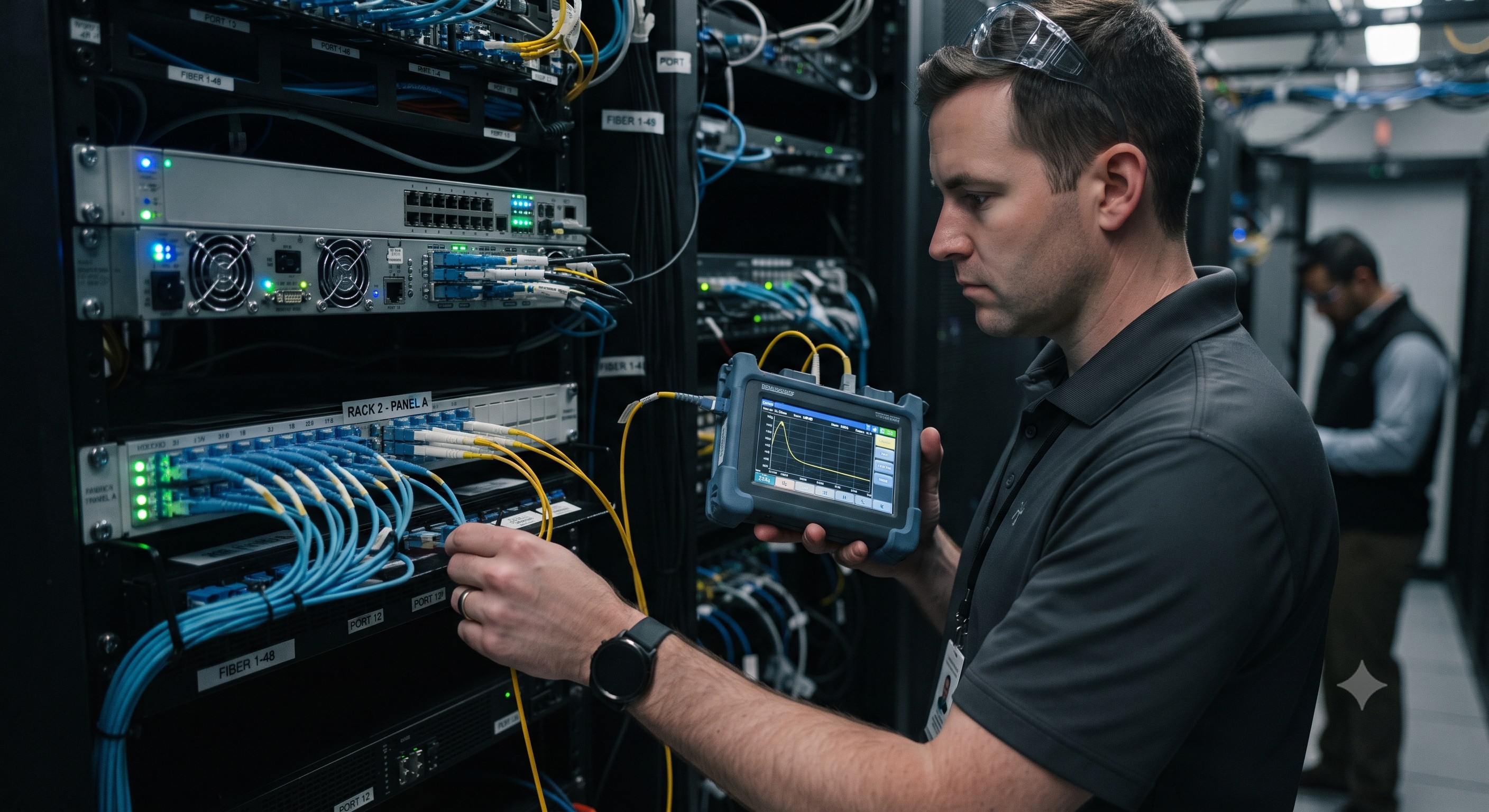
An OTDR is the definitive tool for physically isolating a reflection fault, as it provides a graphical representation of the fiber's attenuation and reflectance over distance. When you connect an OTDR to the subscriber drop, it sends a high-power pulse down the fiber and measures the backscattered and reflected light. A sharp, high peak on the trace (known as a 'reflectance spike') indicates a reflective event, such as an open connector, a crack in the fiber, or a macrobend. By measuring the distance to this spike, you can determine the exact physical location of the fault (e.g., at 1.2km, indicating a problem at the subscriber's demarcation point). This allows you to dispatch field technicians with pinpoint accuracy, avoiding the costly and time-consuming process of replacing the entire drop cable.
Q4: How does a connector contamination cause reflection and what is the proper cleaning procedure?
Dust, oil, or debris on a fiber optic connector ferrule acts as a reflective surface, creating a Fresnel reflection that can cause up to 4% return loss. To resolve this, you must perform a proper cleaning procedure: first, visually inspect the connector end-face using a fiber inspection microscope (adhering to IEC 61300-3-35 standards). If contamination is present, use a dry cleaning cassette (e.g., a CLETOP-style cleaner) to make a single, straight pass across the end-face. Follow this with a wet-dry cleaning process using a lint-free wipe saturated with 99% isopropyl alcohol, immediately followed by a dry wipe. Never use compressed air, as it can introduce static charge and more contaminants. After cleaning, re-inspect the connector to ensure an end-face grade of '1' (no scratches or defects) before reconnecting.
Q5: Can an incompatible optical module cause reflection-like symptoms on the subscriber drop?
Yes, an incompatible SFP/SFP+ module can absolutely cause symptoms that mimic a reflection issue. If a module has incorrect transmit power or a non-standard receiver sensitivity for the specific subscriber drop length (e.g., using a 40km SFP on a 1km link), the receiver can be saturated by the high power, leading to a distorted signal that resembles interference. Furthermore, mismatched wavelength optics (e.g., mixing 1310nm and 1550nm on the same fiber pair) will cause catastrophic signal degradation. Always verify compatibility using the `show interface transceiver supported` command to ensure the module matches the network design specifications (e.g., 1000BASE-LX/LH for long distances). For third-party optics, ensure the 'Digital Diagnostic Monitoring' is correctly calibrated to the switching ASIC.
Q6: What are the steps for a remote loopback test to verify the integrity of a subscriber drop?
Performing a remote loopback test is a two-step process to definitively confirm if the reflection is internal to the switch port or the external subscriber drop. First, configure a local loopback on the switch port using the `loopback interface` command to ensure the port's physical transceiver and ASIC are functioning correctly. If this passes, the problem is external. To test the drop cable, coordinate with the field technician to place a physical loopback plug (or link) at the far end of the subscriber drop. Then, run a BERT (Bit Error Rate Test) using the `test pattern generator` command. If the BERT reports high error counts during this test, it conclusively proves that the subscriber drop cable itself is faulty (due to micro-bends, kinks, or physical damage), enabling you to confidently issue a replacement work order.
Q7: How do I interpret SFP DDM parameters to differentiate between a reflection fault and a fiber break?
Differentiating a reflection fault from a break is straightforward using four key DDM parameters: TX Power, RX Power, Bias Current, and Temperature. In a **fiber break**, the RX Power will drop to approximately -30dBm or -40dBm (indicating no light received), while TX Power and Bias Current remain normal. In a **reflection fault**, the RX Power will often remain within a normal operating range (e.g., -10dBm), but the 'Signal Degrade' and 'Signal Fail' alarms may trigger due to high jitter or low OSNR (Optical Signal-to-Noise Ratio). Additionally, a high reflection will cause the module's internal laser to exhibit temperature fluctuations or increased bias current as it attempts to compensate. If RX Power is normal but errors are high and bias current is stable, the issue is 100% a reflection or impedance mismatch on the cable.
Q8: What is the maximum allowable return loss for a subscriber drop to prevent reflection issues?
The maximum allowable return loss to maintain a healthy signal and prevent reflection-induced errors is -14dB for physical layer components, with the ideal target being less than -20dB (meaning more negative). According to the IEEE 802.3 standard, for a 1000BASE-T or 10GBASE-T copper drop, the return loss must be at least 16.0dB at frequencies up to 250MHz. For fiber, the return loss for a physical contact (PC) polish connector should be ≤ -40dB, and for an Angled Physical Contact (APC) connector, it should be ≤ -60dB. If your OTDR shows a return loss value higher (less negative) than -14dB at the far-end or at any connector, that is a definitive threshold indicating a reflection issue that must be addressed by re-terminating the connector or replacing the drop segment.
Comments
Leave a comment
Post comment


