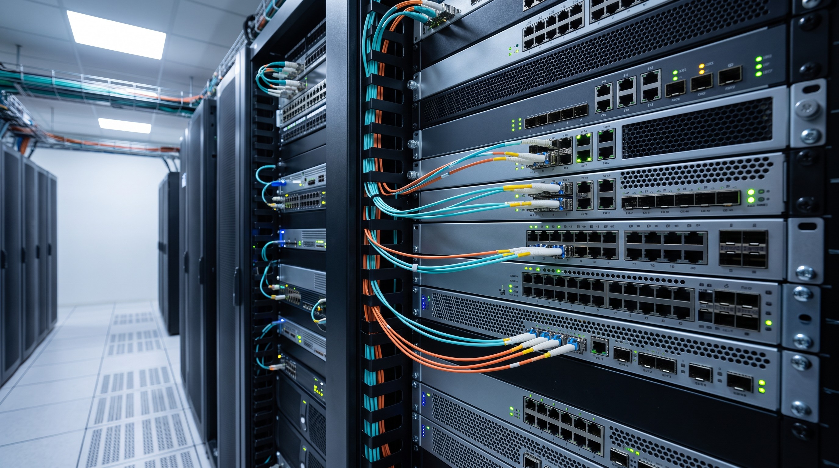
 High-Density Fiber Infrastructure Application Note: Troubleshooting Fiber Optic Macrobending and Connector Contamination Loss Matrix
26 Aug, 2026. Posted by:XPONSHOP
Most Views Posts
The ONT Configuration Status Fails on Huawei MA5608T
2025-10-22 08:59:33
Achieving Line-Rate Forwarding: Buffer Allocation and QoS Optimization in Fiber Network Upgrades
2026-08-26 09:53:54
ZTE GFGH 16-Port GPON Board for ZXA10 C600 Series OLT Guide
2026-03-12 10:11:02
Popular Posts
The Ultimate Guide to 10G Ethernet Ports on ONUs: Architecture, Backplane Bandwidth, and Deployment
2026-09-09 10:40:46
Troubleshooting ONT VoIP Phone: Why Can I Receive Incoming Calls But Cannot Make Outgoing Calls? FAQ
2026-10-08 11:40:04
Why Does the LAN Link Light Remain Solidly Illuminated Even When the Network Cable Is Unplugged? Deep Dive: Internal ASIC Forwarding, Packet Pipelines, and Latency Limits
2026-09-30 10:49:24
PDF Document
2026-05-22 15:51:31
Random Posts
Optimizing 10G Fiber Networks: A Deep Dive into Nokia XGS-PON OLT Class N2 (FWLT-B, 3FE46232BA)
2026-04-23 13:36:22
JUMBO FRAME SUPPORT 9K BYTES - OFFICIAL TECHNICAL OVERVIEW & HARDWARE DATASHEET
2026-05-27 14:05:40
ZTE C300 OLT System Compatibility Matrix with Third-Party Transceiver Modules - Official Technical Overview & Hardware Datasheet
2026-06-26 14:55:48
OLT vs ONT/ONU: Understanding the Two Pillars of Your Fiber Network
2026-05-29 10:30:44
Recent Posts
AI Optical Transceivers vs. Telecom Optical Transceivers: Two ‘Personalities’ of the Same Component
2026-10-30 11:30:33
Overcoming Network Bottlenecks: Enterprise Configuration Manual for Nintendo Switch NAT Type D Resolution
2026-10-30 10:06:06
Cisco Business 350 Series Managed Switch Physical Security and Power Efficiency - Official Technical Overview & Hardware Datasheet
2026-10-30 10:03:46
About
XponShop blog describes some basics for Huawei / ZTE /
Nokia / FiberHome GPON OLT, ONT, SFP, and Site Power...
such as configurations, issue troubleshooting, knowledge
sharing, and keeps updating.
Recent posts
 AI Optical Transceivers vs. Telecom Optical Transceivers: Two ‘Personalities’ of the Same Component
27 Mar, 2025
 Overcoming Network Bottlenecks: Enterprise Configuration Manual for Nintendo Switch NAT Type D Resolution
27 Mar, 2025
 Cisco Business 350 Series Managed Switch Physical Security and Power Efficiency - Official Technical Overview & Hardware Datasheet
27 Mar, 2025
AI Optical Transceivers vs. Telecom Optical Transceivers: Two ‘Personalities’ of the Same Component
27 Mar, 2025
Overcoming Network Bottlenecks: Enterprise Configuration Manual for Nintendo Switch NAT Type D Resolution
27 Mar, 2025
Cisco Business 350 Series Managed Switch Physical Security and Power Efficiency - Official Technical Overview & Hardware Datasheet
27 Mar, 2025
Products from the blog
基本
文件
流程
错误
SQL
调试
- 请求信息 : 2026-11-04 15:17:43 HTTP/2.0 GET : https://www.xponshop.com/blog/high-density-fiber-infrastructure-application-note-troubleshooting-fiber-optic-macrobending-and-connector-contamination-loss-matrix.html
- 运行时间 : 0.320025s [ 吞吐率:3.12req/s ] 内存消耗:1,682.86kb 文件加载:171
- 查询信息 : 0 queries
- 缓存信息 : 0 reads,0 writes
- 会话信息 : SESSION_ID=84b4c1249c4db79f2838fad5c565e22e
- /www/wwwroot/xpshop/public/index.php ( 2.34 KB )
- /www/wwwroot/xpshop/vendor/autoload.php ( 0.78 KB )
- /www/wwwroot/xpshop/vendor/composer/autoload_real.php ( 1.68 KB )
- /www/wwwroot/xpshop/vendor/composer/platform_check.php ( 1.04 KB )
- /www/wwwroot/xpshop/vendor/composer/ClassLoader.php ( 15.99 KB )
- /www/wwwroot/xpshop/vendor/composer/autoload_static.php ( 15.70 KB )
- /www/wwwroot/xpshop/vendor/topthink/think-helper/src/helper.php ( 8.64 KB )
- /www/wwwroot/xpshop/vendor/topthink/think-orm/stubs/load_stubs.php ( 0.17 KB )
- /www/wwwroot/xpshop/vendor/topthink/framework/src/think/Exception.php ( 1.75 KB )
- /www/wwwroot/xpshop/vendor/topthink/framework/src/think/Facade.php ( 2.81 KB )
- /www/wwwroot/xpshop/vendor/symfony/polyfill-mbstring/bootstrap.php ( 8.43 KB )
- /www/wwwroot/xpshop/vendor/symfony/polyfill-mbstring/bootstrap80.php ( 9.93 KB )
- /www/wwwroot/xpshop/vendor/symfony/deprecation-contracts/function.php ( 1.02 KB )
- /www/wwwroot/xpshop/vendor/ezyang/htmlpurifier/library/HTMLPurifier.composer.php ( 0.10 KB )
- /www/wwwroot/xpshop/vendor/hyperf/engine/src/Functions.php ( 0.87 KB )
- /www/wwwroot/xpshop/vendor/ralouphie/getallheaders/src/getallheaders.php ( 1.65 KB )
- /www/wwwroot/xpshop/vendor/symfony/polyfill-php80/bootstrap.php ( 1.54 KB )
- /www/wwwroot/xpshop/vendor/symfony/translation/Resources/functions.php ( 0.57 KB )
- /www/wwwroot/xpshop/vendor/thinkcmf/cmf/src/common.php ( 105.49 KB )
- /www/wwwroot/xpshop/vendor/yansongda/supports/src/Functions.php ( 1.59 KB )
- /www/wwwroot/xpshop/vendor/guzzlehttp/guzzle/src/functions_include.php ( 0.16 KB )
- /www/wwwroot/xpshop/vendor/guzzlehttp/guzzle/src/functions.php ( 5.72 KB )
- /www/wwwroot/xpshop/vendor/topthink/think-queue/src/common.php ( 1.04 KB )
- /www/wwwroot/xpshop/vendor/yansongda/pay/src/Functions.php ( 11.15 KB )
- /www/wwwroot/xpshop/vendor/thinkcmf/cmf/think/App.php ( 18.43 KB )
- /www/wwwroot/xpshop/vendor/topthink/framework/src/think/Container.php ( 15.93 KB )
- /www/wwwroot/xpshop/vendor/psr/container/src/ContainerInterface.php ( 1.06 KB )
- /www/wwwroot/xpshop/vendor/thinkcmf/cmf-app/src/provider.php ( 0.25 KB )
- /www/wwwroot/xpshop/vendor/thinkcmf/cmf/think/Http.php ( 7.47 KB )
- /www/wwwroot/xpshop/vendor/topthink/think-helper/src/helper/Str.php ( 7.51 KB )
- /www/wwwroot/xpshop/vendor/topthink/framework/src/think/Env.php ( 4.87 KB )
- /www/wwwroot/xpshop/app/common.php ( 3.15 KB )
- /www/wwwroot/xpshop/vendor/topthink/framework/src/helper.php ( 19.12 KB )
- /www/wwwroot/xpshop/vendor/topthink/framework/src/think/Config.php ( 4.79 KB )
- /www/wwwroot/xpshop/vendor/thinkcmf/cmf/src/config/app.php ( 1.39 KB )
- /www/wwwroot/xpshop/vendor/topthink/framework/src/think/facade/Env.php ( 1.71 KB )
- /www/wwwroot/xpshop/vendor/thinkcmf/cmf/src/config/cache.php ( 0.83 KB )
- /www/wwwroot/xpshop/vendor/thinkcmf/cmf/src/config/console.php ( 1.14 KB )
- /www/wwwroot/xpshop/vendor/thinkcmf/cmf/src/config/log.php ( 1.41 KB )
- /www/wwwroot/xpshop/vendor/thinkcmf/cmf/src/config/route.php ( 1.59 KB )
- /www/wwwroot/xpshop/vendor/thinkcmf/cmf/src/config/template.php ( 0.65 KB )
- /www/wwwroot/xpshop/vendor/thinkcmf/cmf/src/config/view.php ( 1.09 KB )
- /www/wwwroot/xpshop/config/app.php ( 0.09 KB )
- /www/wwwroot/xpshop/config/queue.php ( 1.33 KB )
- /www/wwwroot/xpshop/data/config/config.php ( 0.09 KB )
- /www/wwwroot/xpshop/data/config/database.php ( 2.40 KB )
- /www/wwwroot/xpshop/data/config/lang.php ( 0.46 KB )
- /www/wwwroot/xpshop/vendor/thinkcmf/cmf-app/src/event.php ( 0.58 KB )
- /www/wwwroot/xpshop/vendor/topthink/framework/src/think/Event.php ( 7.23 KB )
- /www/wwwroot/xpshop/app/event.php ( 0.25 KB )
- /www/wwwroot/xpshop/vendor/topthink/framework/src/think/Lang.php ( 7.49 KB )
- /www/wwwroot/xpshop/vendor/thinkcmf/cmf/src/listener/InitHookListener.php ( 2.59 KB )
- /www/wwwroot/xpshop/vendor/topthink/framework/src/think/facade/Route.php ( 4.76 KB )
- /www/wwwroot/xpshop/vendor/thinkcmf/cmf/think/Route.php ( 24.37 KB )
- /www/wwwroot/xpshop/vendor/topthink/framework/src/think/route/RuleName.php ( 5.55 KB )
- /www/wwwroot/xpshop/vendor/topthink/framework/src/think/route/Domain.php ( 5.71 KB )
- /www/wwwroot/xpshop/vendor/topthink/framework/src/think/route/RuleGroup.php ( 13.91 KB )
- /www/wwwroot/xpshop/vendor/thinkcmf/cmf/think/route/Rule.php ( 24.55 KB )
- /www/wwwroot/xpshop/vendor/topthink/framework/src/think/route/RuleItem.php ( 9.50 KB )
- /www/wwwroot/xpshop/vendor/topthink/framework/src/think/facade/Cache.php ( 2.11 KB )
- /www/wwwroot/xpshop/vendor/topthink/framework/src/think/Cache.php ( 5.11 KB )
- /www/wwwroot/xpshop/vendor/topthink/framework/src/think/Manager.php ( 4.09 KB )
- /www/wwwroot/xpshop/vendor/psr/simple-cache/src/CacheInterface.php ( 4.82 KB )
- /www/wwwroot/xpshop/vendor/topthink/think-helper/src/helper/Arr.php ( 16.72 KB )
- /www/wwwroot/xpshop/vendor/topthink/framework/src/think/cache/driver/File.php ( 7.89 KB )
- /www/wwwroot/xpshop/vendor/topthink/framework/src/think/cache/Driver.php ( 8.52 KB )
- /www/wwwroot/xpshop/vendor/topthink/framework/src/think/contract/CacheHandlerInterface.php ( 2.06 KB )
- /www/wwwroot/xpshop/vendor/topthink/framework/src/think/facade/Event.php ( 1.83 KB )
- /www/wwwroot/xpshop/app/listener/InitHookListener.php ( 0.82 KB )
- /www/wwwroot/xpshop/app/portal/route.php ( 7.83 KB )
- /www/wwwroot/xpshop/vendor/topthink/framework/src/think/Request.php ( 56.59 KB )
- /www/wwwroot/xpshop/vendor/topthink/think-orm/src/facade/Db.php ( 0.96 KB )
- /www/wwwroot/xpshop/vendor/topthink/framework/src/think/Db.php ( 2.99 KB )
- /www/wwwroot/xpshop/vendor/topthink/think-orm/src/DbManager.php ( 8.72 KB )
- /www/wwwroot/xpshop/vendor/topthink/framework/src/think/Log.php ( 6.51 KB )
- /www/wwwroot/xpshop/vendor/psr/log/src/LoggerTrait.php ( 2.79 KB )
- /www/wwwroot/xpshop/vendor/psr/log/src/LoggerInterface.php ( 2.80 KB )
- /www/wwwroot/xpshop/vendor/topthink/think-orm/src/db/connector/Mysql.php ( 4.50 KB )
- /www/wwwroot/xpshop/vendor/topthink/think-orm/src/db/PDOConnection.php ( 53.54 KB )
- /www/wwwroot/xpshop/vendor/topthink/think-orm/src/db/Connection.php ( 9.19 KB )
- /www/wwwroot/xpshop/vendor/topthink/think-orm/src/db/ConnectionInterface.php ( 5.08 KB )
- /www/wwwroot/xpshop/vendor/topthink/think-orm/src/db/builder/Mysql.php ( 17.07 KB )
- /www/wwwroot/xpshop/vendor/topthink/think-orm/src/db/Builder.php ( 23.03 KB )
- /www/wwwroot/xpshop/vendor/topthink/think-orm/src/db/BaseBuilder.php ( 28.23 KB )
- /www/wwwroot/xpshop/vendor/topthink/think-orm/src/db/Query.php ( 14.82 KB )
- /www/wwwroot/xpshop/vendor/topthink/think-orm/src/db/BaseQuery.php ( 42.79 KB )
- /www/wwwroot/xpshop/vendor/topthink/think-orm/src/db/concern/TimeFieldQuery.php ( 7.65 KB )
- /www/wwwroot/xpshop/vendor/topthink/think-orm/src/db/concern/AggregateQuery.php ( 3.39 KB )
- /www/wwwroot/xpshop/vendor/topthink/think-orm/src/db/concern/ModelRelationQuery.php ( 19.62 KB )
- /www/wwwroot/xpshop/vendor/topthink/think-orm/src/db/concern/ParamsBind.php ( 3.80 KB )
- /www/wwwroot/xpshop/vendor/topthink/think-orm/src/db/concern/ResultOperation.php ( 6.90 KB )
- /www/wwwroot/xpshop/vendor/topthink/think-orm/src/db/concern/Transaction.php ( 2.90 KB )
- /www/wwwroot/xpshop/vendor/topthink/think-orm/src/db/concern/WhereQuery.php ( 18.40 KB )
- /www/wwwroot/xpshop/vendor/topthink/think-orm/src/db/concern/JoinAndViewQuery.php ( 7.23 KB )
- /www/wwwroot/xpshop/vendor/topthink/think-orm/src/db/concern/TableFieldInfo.php ( 2.56 KB )
- /www/wwwroot/xpshop/vendor/topthink/framework/src/think/log/driver/File.php ( 6.38 KB )
- /www/wwwroot/xpshop/vendor/topthink/framework/src/think/contract/LogHandlerInterface.php ( 0.89 KB )
- /www/wwwroot/xpshop/vendor/topthink/framework/src/think/log/Channel.php ( 4.04 KB )
- /www/wwwroot/xpshop/vendor/topthink/framework/src/think/event/LogRecord.php ( 0.89 KB )
- /www/wwwroot/xpshop/vendor/topthink/framework/src/think/initializer/Error.php ( 3.38 KB )
- /www/wwwroot/xpshop/vendor/topthink/framework/src/think/initializer/RegisterService.php ( 1.37 KB )
- /www/wwwroot/xpshop/vendor/services.php ( 0.25 KB )
- /www/wwwroot/xpshop/vendor/topthink/framework/src/think/service/PaginatorService.php ( 1.57 KB )
- /www/wwwroot/xpshop/vendor/topthink/framework/src/think/Service.php ( 1.70 KB )
- /www/wwwroot/xpshop/vendor/topthink/framework/src/think/service/ValidateService.php ( 1.02 KB )
- /www/wwwroot/xpshop/vendor/topthink/framework/src/think/service/ModelService.php ( 1.80 KB )
- /www/wwwroot/xpshop/vendor/thinkcmf/cmf-appstore/src/AppStoreService.php ( 1.12 KB )
- /www/wwwroot/xpshop/vendor/topthink/think-queue/src/queue/Service.php ( 1.29 KB )
- /www/wwwroot/xpshop/vendor/topthink/think-trace/src/Service.php ( 0.79 KB )
- /www/wwwroot/xpshop/vendor/topthink/framework/src/think/Middleware.php ( 6.89 KB )
- /www/wwwroot/xpshop/vendor/xia/migration/src/Service.php ( 2.02 KB )
- /www/wwwroot/xpshop/vendor/topthink/framework/src/think/initializer/BootService.php ( 0.79 KB )
- /www/wwwroot/xpshop/vendor/topthink/think-orm/src/Paginator.php ( 12.21 KB )
- /www/wwwroot/xpshop/vendor/topthink/framework/src/think/Validate.php ( 48.38 KB )
- /www/wwwroot/xpshop/vendor/topthink/think-orm/src/Model.php ( 27.82 KB )
- /www/wwwroot/xpshop/vendor/topthink/think-orm/src/model/concern/Attribute.php ( 19.62 KB )
- /www/wwwroot/xpshop/vendor/topthink/think-orm/src/model/concern/RelationShip.php ( 27.32 KB )
- /www/wwwroot/xpshop/vendor/topthink/think-orm/src/model/concern/ModelEvent.php ( 2.33 KB )
- /www/wwwroot/xpshop/vendor/topthink/think-orm/src/model/concern/TimeStamp.php ( 5.92 KB )
- /www/wwwroot/xpshop/vendor/topthink/think-orm/src/model/concern/AutoWriteId.php ( 1.50 KB )
- /www/wwwroot/xpshop/vendor/topthink/think-orm/src/model/concern/Conversion.php ( 11.25 KB )
- /www/wwwroot/xpshop/vendor/topthink/think-helper/src/contract/Arrayable.php ( 0.10 KB )
- /www/wwwroot/xpshop/vendor/topthink/think-helper/src/contract/Jsonable.php ( 0.14 KB )
- /www/wwwroot/xpshop/vendor/thinkcmf/cmf/think/Console.php ( 23.46 KB )
- /www/wwwroot/xpshop/vendor/thinkcmf/cmf-app/src/middleware.php ( 0.26 KB )
- /www/wwwroot/xpshop/vendor/topthink/framework/src/think/Pipeline.php ( 2.71 KB )
- /www/wwwroot/xpshop/vendor/topthink/think-trace/src/TraceDebug.php ( 3.05 KB )
- /www/wwwroot/xpshop/vendor/thinkcmf/cmf/src/middleware/LangDetect.php ( 5.94 KB )
- /www/wwwroot/xpshop/vendor/topthink/framework/src/think/Cookie.php ( 6.19 KB )
- /www/wwwroot/xpshop/vendor/topthink/framework/src/think/middleware/SessionInit.php ( 2.01 KB )
- /www/wwwroot/xpshop/vendor/topthink/framework/src/think/Session.php ( 1.86 KB )
- /www/wwwroot/xpshop/vendor/topthink/framework/src/think/session/driver/File.php ( 6.52 KB )
- /www/wwwroot/xpshop/vendor/topthink/framework/src/think/contract/SessionHandlerInterface.php ( 0.89 KB )
- /www/wwwroot/xpshop/vendor/topthink/framework/src/think/session/Store.php ( 7.37 KB )
- /www/wwwroot/xpshop/data/route/route.php ( 10.75 KB )
- /www/wwwroot/xpshop/vendor/thinkcmf/cmf/think/route/dispatch/Controller.php ( 7.73 KB )
- /www/wwwroot/xpshop/vendor/topthink/framework/src/think/route/Dispatch.php ( 6.29 KB )
- /www/wwwroot/xpshop/vendor/thinkcmf/cmf/src/listener/ModuleInitListener.php ( 2.20 KB )
- /www/wwwroot/xpshop/vendor/topthink/think-helper/src/Collection.php ( 17.14 KB )
- /www/wwwroot/xpshop/app/portal/controller/BlogController.php ( 5.17 KB )
- /www/wwwroot/xpshop/vendor/thinkcmf/cmf/src/controller/HomeBaseController.php ( 13.79 KB )
- /www/wwwroot/xpshop/vendor/thinkcmf/cmf/src/controller/BaseController.php ( 10.69 KB )
- /www/wwwroot/xpshop/vendor/thinkcmf/cmf/think/View.php ( 5.21 KB )
- /www/wwwroot/xpshop/vendor/topthink/framework/src/think/facade/Config.php ( 1.41 KB )
- /www/wwwroot/xpshop/vendor/topthink/framework/src/think/facade/Cookie.php ( 1.52 KB )
- /www/wwwroot/xpshop/vendor/thinkcmf/cmf/think/view/driver/Think.php ( 8.67 KB )
- /www/wwwroot/xpshop/vendor/thinkcmf/cmf/think/Template.php ( 55.14 KB )
- /www/wwwroot/xpshop/vendor/thinkcmf/cmf/think/template/driver/File.php ( 2.42 KB )
- /www/wwwroot/xpshop/vendor/thinkcmf/cmf-app/src/admin/model/LinkModel.php ( 0.92 KB )
- /www/wwwroot/xpshop/vendor/topthink/think-orm/src/model/Collection.php ( 6.93 KB )
- /www/wwwroot/xpshop/api/portal/model/SocialModel.php ( 2.51 KB )
- /www/wwwroot/xpshop/vendor/thinkcmf/cmf/src/listener/HomeLangListener.php ( 3.40 KB )
- /www/wwwroot/xpshop/vendor/topthink/framework/src/think/facade/Session.php ( 1.84 KB )
- /www/wwwroot/xpshop/app/listener/HomeInitListener.php ( 3.09 KB )
- /www/wwwroot/xpshop/api/portal/model/NewsModel.php ( 1.73 KB )
- /www/wwwroot/xpshop/vendor/thinkcmf/cmf/src/lib/Storage.php ( 4.40 KB )
- /www/wwwroot/xpshop/vendor/thinkcmf/cmf/src/lib/storage/Local.php ( 2.97 KB )
- /www/wwwroot/xpshop/api/portal/model/PortalPostModel.php ( 26.71 KB )
- /www/wwwroot/xpshop/vendor/topthink/think-orm/src/db/Raw.php ( 1.28 KB )
- /www/wwwroot/xpshop/vendor/thinkcmf/cmf-app/src/admin/model/ThemeModel.php ( 12.56 KB )
- /www/wwwroot/xpshop/vendor/thinkcmf/cmf-app/src/admin/model/ThemeFileModel.php ( 1.96 KB )
- /www/wwwroot/xpshop/data/runtime/temp/english_6df7f0f34cddea77df5aa1fa9591dd7b.php ( 62.29 KB )
- /www/wwwroot/xpshop/vendor/thinkcmf/cmf-app/src/admin/model/NavMenuModel.php ( 9.60 KB )
- /www/wwwroot/xpshop/vendor/thinkcmf/cmf-extend/src/tree/Tree.php ( 10.30 KB )
- /www/wwwroot/xpshop/vendor/thinkcmf/cmf-app/src/admin/model/RouteModel.php ( 8.92 KB )
- /www/wwwroot/xpshop/app/portal/url.php ( 1.60 KB )
- /www/wwwroot/xpshop/vendor/thinkcmf/cmf-app/src/user/url.php ( 1.01 KB )
- /www/wwwroot/xpshop/vendor/thinkcmf/cmf/think/route/Url.php ( 17.14 KB )
- /www/wwwroot/xpshop/vendor/topthink/framework/src/think/Response.php ( 9.05 KB )
- /www/wwwroot/xpshop/vendor/topthink/framework/src/think/response/Html.php ( 1.01 KB )
- /www/wwwroot/xpshop/vendor/topthink/think-trace/src/Html.php ( 4.49 KB )
- CONNECT:[ UseTime:0.000296s ] mysql:host=127.0.0.1;port=3306;dbname=xpshop;charset=utf8mb4
- SHOW FULL COLUMNS FROM `cmf_news` [ RunTime:0.001215s ]
- SELECT * FROM `cmf_news` WHERE `news_status` = 1 AND `slug` = 'high-density-fiber-infrastructure-application-note-troubleshooting-fiber-optic-macrobending-and-connector-contamination-loss-matrix' LIMIT 1 [ RunTime:0.003112s ]
- SHOW FULL COLUMNS FROM `cmf_link` [ RunTime:0.001185s ]
- SELECT * FROM `cmf_link` WHERE `status` = 1 [ RunTime:0.000286s ]
- SHOW FULL COLUMNS FROM `cmf_social` [ RunTime:0.001170s ]
- SELECT * FROM `cmf_social` WHERE `status` = 1 [ RunTime:0.000251s ]
- SHOW FULL COLUMNS FROM `cmf_portal_category` [ RunTime:0.001200s ]
- SELECT * FROM `cmf_portal_category` WHERE `module_id` = 2 ORDER BY `list_order` ASC [ RunTime:0.000477s ]
- SHOW FULL COLUMNS FROM `cmf_countries` [ RunTime:0.000946s ]
- SELECT * FROM `cmf_countries` [ RunTime:0.000358s ]
- SELECT * FROM `cmf_news` WHERE `slug` = 'high-density-fiber-infrastructure-application-note-troubleshooting-fiber-optic-macrobending-and-connector-contamination-loss-matrix' LIMIT 1 [ RunTime:0.002931s ]
- SHOW FULL COLUMNS FROM `cmf_option` [ RunTime:0.000993s ]
- SELECT `option_value` FROM `cmf_option` WHERE `option_name` = 'storage' LIMIT 1 [ RunTime:0.000209s ]
- SELECT * FROM `cmf_news` WHERE `news_status` = 1 ORDER BY `create_time` DESC LIMIT 3 [ RunTime:0.004109s ]
- SHOW FULL COLUMNS FROM `cmf_portal_post` [ RunTime:0.001583s ]
- SELECT * FROM `cmf_portal_post` WHERE 0 = 1 AND `post_type` = 1 [ RunTime:0.000299s ]
- SHOW FULL COLUMNS FROM `cmf_news_comment` [ RunTime:0.000993s ]
- SELECT * FROM `cmf_news_comment` WHERE `news_id` = 822 AND `status` = 1 ORDER BY `create_time` ASC [ RunTime:0.000261s ]
- SELECT * FROM `cmf_news` ORDER BY RAND() LIMIT 5 [ RunTime:0.008103s ]
- SELECT * FROM `cmf_news` ORDER BY RAND() LIMIT 5 [ RunTime:0.007681s ]
- SELECT * FROM `cmf_news` ORDER BY RAND() LIMIT 5 [ RunTime:0.007371s ]
- SELECT * FROM `cmf_news` ORDER BY `create_time` DESC LIMIT 5 [ RunTime:0.004130s ]
- SHOW FULL COLUMNS FROM `cmf_theme_file` [ RunTime:0.001165s ]
- SELECT * FROM `cmf_theme_file` WHERE `theme` = 'default' AND `file` = 'portal/404' LIMIT 1 [ RunTime:0.000324s ]
- UPDATE `cmf_theme_file` SET `theme` = 'default' , `action` = 'portal/Index/Notfound' , `file` = 'portal/404' , `name` = '首页' , `more` = '{\"widgets_blocks\":{\"top\":{\"title\":\"\\u9876\\u90e8\",\"widgets\":{\"top_nav_202206300003\":{\"title\":\"\\u9876\\u90e8\\u5bfc\\u822a\",\"name\":\"nav\",\"display\":\"1\",\"public_widget_id\":\"top_nav\",\"version\":\"1.0.0\",\"action\":\"\",\"vars\":{\"company_name\":\"ThinkCMF\",\"nav_id\":\"\"}}}},\"body\":{\"title\":\"\\u4e3b\\u4f53\",\"widgets\":{\"home_slider_202206300003\":{\"title\":\"\\u9996\\u9875\\u5e7b\\u706f\\u7247\",\"name\":\"slider\",\"display\":\"1\",\"version\":\"1.0.0\",\"action\":\"\",\"vars\":{\"slide_id\":\"\",\"fullscreen\":1}},\"home_features_202206300003\":{\"title\":\"\\u4ea7\\u54c1\\u7279\\u6027\",\"name\":\"features\",\"display\":\"1\",\"version\":\"1.0.0\",\"action\":\"\",\"vars\":{\"sub_title\":\"Quickly understand the ThinkCMF\",\"features\":[{\"title\":\"MVC\\u5206\\u5c42\\u6a21\\u5f0f\",\"icon\":\"bars\",\"content\":\"\\u4f7f\\u7528MVC\\u5e94\\u7528\\u7a0b\\u5e8f\\u88ab\\u5206\\u6210\\u4e09\\u4e2a\\u6838\\u5fc3\\u90e8\\u4ef6\\uff1a\\u6a21\\u578b\\uff08M\\uff09\\u3001\\u89c6\\u56fe\\uff08V\\uff09\\u3001\\u63a7\\u5236\\u5668\\uff08C\\uff09\\uff0c\\u4ed6\\u4e0d\\u662f\\u4e00\\u4e2a\\u65b0\\u7684\\u6982\\u5ff5\\uff0c\\u53ea\\u662fThinkCMF\\u5c06\\u5176\\u53d1\\u6325\\u5230\\u4e86\\u6781\\u81f4\\u3002\"},{\"title\":\"\\u7528\\u6237\\u7ba1\\u7406\",\"icon\":\"group\",\"content\":\"ThinkCMF\\u5185\\u7f6e\\u4e86\\u7075\\u6d3b\\u7684\\u7528\\u6237\\u7ba1\\u7406\\u65b9\\u5f0f\\uff0c\\u5e76\\u53ef\\u76f4\\u63a5\\u4e0e\\u7b2c\\u4e09\\u65b9\\u7ad9\\u70b9\\u8fdb\\u884c\\u4e92\\u8054\\u4e92\\u901a\\uff0c\\u5982\\u679c\\u4f60\\u613f\\u610f\\u751a\\u81f3\\u53ef\\u4ee5\\u5bf9\\u5355\\u4e2a\\u7528\\u6237\\u6216\\u7fa4\\u4f53\\u7528\\u6237\\u7684\\u884c\\u4e3a\\u8fdb\\u884c\\u8bb0\\u5f55\\u53ca\\u5206\\u4eab\\uff0c\\u4e3a\\u60a8\\u7684\\u8fd0\\u8425\\u51b3\\u7b56\\u63d0\\u4f9b\\u6709\\u6548\\u53c2\\u8003\\u6570\\u636e\\u3002\"},{\"title\":\"\\u4e91\\u7aef\\u90e8\\u7f72\",\"icon\":\"cloud\",\"content\":\"\\u901a\\u8fc7\\u9a71\\u52a8\\u7684\\u65b9\\u5f0f\\u53ef\\u4ee5\\u8f7b\\u677e\\u652f\\u6301\\u4e91\\u5e73\\u53f0\\u7684\\u90e8\\u7f72\\uff0c\\u8ba9\\u4f60\\u7684\\u7f51\\u7ad9\\u65e0\\u7f1d\\u8fc1\\u79fb\\uff0c\\u5185\\u7f6e\\u5df2\\u7ecf\\u652f\\u6301SAE\\u3001BAE\\uff0c\\u6b63\\u5f0f\\u7248\\u5c06\\u5bf9\\u4e91\\u7aef\\u90e8\\u7f72\\u8fdb\\u884c\\u8fdb\\u4e00\\u6b65\\u4f18\\u5316\\u3002\"},{\"title\":\"\\u5b89\\u5168\\u7b56\\u7565\",\"icon\":\"heart\",\"content\":\"\\u63d0\\u4f9b\\u7684\\u7a33\\u5065\\u7684\\u5b89\\u5168\\u7b56\\u7565\\uff0c\\u5305\\u62ec\\u5907\\u4efd\\u6062\\u590d\\uff0c\\u5bb9\\u9519\\uff0c\\u9632\\u6cbb\\u6076\\u610f\\u653b\\u51fb\\u767b\\u9646\\uff0c\\u7f51\\u9875\\u9632\\u7be1\\u6539\\u7b49\\u591a\\u9879\\u5b89\\u5168\\u7ba1\\u7406\\u529f\\u80fd\\uff0c\\u4fdd\\u8bc1\\u7cfb\\u7edf\\u5b89\\u5168\\uff0c\\u53ef\\u9760\\uff0c\\u7a33\\u5b9a\\u7684\\u8fd0\\u884c\\u3002\"},{\"title\":\"\\u5e94\\u7528\\u6a21\\u5757\\u5316\",\"icon\":\"cubes\",\"content\":\"\\u63d0\\u51fa\\u5168\\u65b0\\u7684\\u5e94\\u7528\\u6a21\\u5f0f\\u8fdb\\u884c\\u6269\\u5c55\\uff0c\\u4e0d\\u7ba1\\u662f\\u4f60\\u5f00\\u53d1\\u4e00\\u4e2a\\u5c0f\\u529f\\u80fd\\u8fd8\\u662f\\u4e00\\u4e2a\\u5168\\u65b0\\u7684\\u7ad9\\u70b9\\uff0c\\u5728ThinkCMF\\u4e2d\\u4f60\\u53ea\\u662f\\u589e\\u52a0\\u4e86\\u4e00\\u4e2aAPP\\uff0c\\u6bcf\\u4e2a\\u72ec\\u7acb\\u8fd0\\u884c\\u4e92\\u4e0d\\u5f71\\u54cd\\uff0c\\u4fbf\\u4e8e\\u7075\\u6d3b\\u6269\\u5c55\\u548c\\u4e8c\\u6b21\\u5f00\\u53d1\\u3002\"},{\"title\":\"\\u514d\\u8d39\\u5f00\\u6e90\",\"icon\":\"certificate\",\"content\":\"\\u4ee3\\u7801\\u9075\\u5faaApache2\\u5f00\\u6e90\\u534f\\u8bae\\uff0c\\u514d\\u8d39\\u4f7f\\u7528\\uff0c\\u5bf9\\u5546\\u4e1a\\u7528\\u6237\\u4e5f\\u65e0\\u4efb\\u4f55\\u9650\\u5236\\u3002\"}]}},\"home_last_news_202206300003\":{\"title\":\"\\u6700\\u65b0\\u8d44\\u8baf\",\"name\":\"last_news\",\"display\":\"1\",\"version\":\"1.0.0\",\"action\":\"\",\"vars\":{\"last_news_category_id\":\"\"}},\"home_last_news_202206300004\":{\"title\":\"\\u6700\\u65b0\\u8d44\\u8baf\",\"name\":\"last_news\",\"display\":\"1\",\"version\":\"1.0.0\",\"action\":\"\",\"vars\":{\"last_news_category_id\":\"\"}}}},\"footer\":{\"title\":\"\\u5e95\\u90e8\",\"widgets\":{\"home_footer_202206300003\":{\"title\":\"\\u5e95\\u90e8\",\"name\":\"footer\",\"display\":\"1\",\"public_widget_id\":\"footer\",\"version\":\"1.0.0\",\"action\":\"\",\"vars\":{\"company_name\":\"ThinkCMF\",\"nav_id\":\"2\"}}}}}}' , `config_more` = '{\"widgets_blocks\":{\"top\":{\"title\":\"\\u9876\\u90e8\",\"widgets\":{\"top_nav_202206300003\":{\"title\":\"\\u9876\\u90e8\\u5bfc\\u822a\",\"name\":\"nav\",\"display\":\"1\",\"public_widget_id\":\"top_nav\"}}},\"body\":{\"title\":\"\\u4e3b\\u4f53\",\"widgets\":{\"home_slider_202206300003\":{\"title\":\"\\u9996\\u9875\\u5e7b\\u706f\\u7247\",\"name\":\"slider\",\"display\":\"1\"},\"home_features_202206300003\":{\"title\":\"\\u4ea7\\u54c1\\u7279\\u6027\",\"name\":\"features\",\"display\":\"1\"},\"home_last_news_202206300003\":{\"title\":\"\\u6700\\u65b0\\u8d44\\u8baf\",\"name\":\"last_news\",\"display\":\"1\"},\"home_last_news_202206300004\":{\"title\":\"\\u6700\\u65b0\\u8d44\\u8baf\",\"name\":\"last_news\",\"display\":\"1\"}}},\"footer\":{\"title\":\"\\u5e95\\u90e8\",\"widgets\":{\"home_footer_202206300003\":{\"title\":\"\\u5e95\\u90e8\",\"name\":\"footer\",\"display\":\"1\",\"public_widget_id\":\"footer\"}}}}}' , `description` = '首页模板文件' , `is_public` = 0 , `list_order` = '5' WHERE `theme` = 'default' AND `file` = 'portal/404' [ RunTime:0.008552s ]
- SELECT * FROM `cmf_theme_file` WHERE `theme` = 'default' AND `file` = 'portal/about' LIMIT 1 [ RunTime:0.000274s ]
- UPDATE `cmf_theme_file` SET `theme` = 'default' , `action` = 'portal/Index/index' , `file` = 'portal/about' , `name` = '首页' , `more` = '{\"widgets_blocks\":{\"top\":{\"title\":\"\\u9876\\u90e8\",\"widgets\":{\"top_nav_202206300003\":{\"title\":\"\\u9876\\u90e8\\u5bfc\\u822a\",\"name\":\"nav\",\"display\":\"1\",\"public_widget_id\":\"top_nav\",\"version\":\"1.0.0\",\"action\":\"\",\"vars\":{\"company_name\":\"ThinkCMF\",\"nav_id\":\"\"}}}},\"body\":{\"title\":\"\\u4e3b\\u4f53\",\"widgets\":{\"home_slider_202206300003\":{\"title\":\"home\",\"name\":\"slider\",\"display\":\"1\",\"vars\":{\"slide_id\":\"23\",\"fullscreen\":1}},\"home_features_202206300003\":{\"title\":\"\\u4ea7\\u54c1\\u7279\\u6027\",\"name\":\"features\",\"display\":\"1\",\"version\":\"1.0.0\",\"action\":\"\",\"vars\":{\"sub_title\":\"Quickly understand the ThinkCMF\",\"features\":[{\"title\":\"MVC\\u5206\\u5c42\\u6a21\\u5f0f\",\"icon\":\"bars\",\"content\":\"\\u4f7f\\u7528MVC\\u5e94\\u7528\\u7a0b\\u5e8f\\u88ab\\u5206\\u6210\\u4e09\\u4e2a\\u6838\\u5fc3\\u90e8\\u4ef6\\uff1a\\u6a21\\u578b\\uff08M\\uff09\\u3001\\u89c6\\u56fe\\uff08V\\uff09\\u3001\\u63a7\\u5236\\u5668\\uff08C\\uff09\\uff0c\\u4ed6\\u4e0d\\u662f\\u4e00\\u4e2a\\u65b0\\u7684\\u6982\\u5ff5\\uff0c\\u53ea\\u662fThinkCMF\\u5c06\\u5176\\u53d1\\u6325\\u5230\\u4e86\\u6781\\u81f4\\u3002\"},{\"title\":\"\\u7528\\u6237\\u7ba1\\u7406\",\"icon\":\"group\",\"content\":\"ThinkCMF\\u5185\\u7f6e\\u4e86\\u7075\\u6d3b\\u7684\\u7528\\u6237\\u7ba1\\u7406\\u65b9\\u5f0f\\uff0c\\u5e76\\u53ef\\u76f4\\u63a5\\u4e0e\\u7b2c\\u4e09\\u65b9\\u7ad9\\u70b9\\u8fdb\\u884c\\u4e92\\u8054\\u4e92\\u901a\\uff0c\\u5982\\u679c\\u4f60\\u613f\\u610f\\u751a\\u81f3\\u53ef\\u4ee5\\u5bf9\\u5355\\u4e2a\\u7528\\u6237\\u6216\\u7fa4\\u4f53\\u7528\\u6237\\u7684\\u884c\\u4e3a\\u8fdb\\u884c\\u8bb0\\u5f55\\u53ca\\u5206\\u4eab\\uff0c\\u4e3a\\u60a8\\u7684\\u8fd0\\u8425\\u51b3\\u7b56\\u63d0\\u4f9b\\u6709\\u6548\\u53c2\\u8003\\u6570\\u636e\\u3002\"},{\"title\":\"\\u4e91\\u7aef\\u90e8\\u7f72\",\"icon\":\"cloud\",\"content\":\"\\u901a\\u8fc7\\u9a71\\u52a8\\u7684\\u65b9\\u5f0f\\u53ef\\u4ee5\\u8f7b\\u677e\\u652f\\u6301\\u4e91\\u5e73\\u53f0\\u7684\\u90e8\\u7f72\\uff0c\\u8ba9\\u4f60\\u7684\\u7f51\\u7ad9\\u65e0\\u7f1d\\u8fc1\\u79fb\\uff0c\\u5185\\u7f6e\\u5df2\\u7ecf\\u652f\\u6301SAE\\u3001BAE\\uff0c\\u6b63\\u5f0f\\u7248\\u5c06\\u5bf9\\u4e91\\u7aef\\u90e8\\u7f72\\u8fdb\\u884c\\u8fdb\\u4e00\\u6b65\\u4f18\\u5316\\u3002\"},{\"title\":\"\\u5b89\\u5168\\u7b56\\u7565\",\"icon\":\"heart\",\"content\":\"\\u63d0\\u4f9b\\u7684\\u7a33\\u5065\\u7684\\u5b89\\u5168\\u7b56\\u7565\\uff0c\\u5305\\u62ec\\u5907\\u4efd\\u6062\\u590d\\uff0c\\u5bb9\\u9519\\uff0c\\u9632\\u6cbb\\u6076\\u610f\\u653b\\u51fb\\u767b\\u9646\\uff0c\\u7f51\\u9875\\u9632\\u7be1\\u6539\\u7b49\\u591a\\u9879\\u5b89\\u5168\\u7ba1\\u7406\\u529f\\u80fd\\uff0c\\u4fdd\\u8bc1\\u7cfb\\u7edf\\u5b89\\u5168\\uff0c\\u53ef\\u9760\\uff0c\\u7a33\\u5b9a\\u7684\\u8fd0\\u884c\\u3002\"},{\"title\":\"\\u5e94\\u7528\\u6a21\\u5757\\u5316\",\"icon\":\"cubes\",\"content\":\"\\u63d0\\u51fa\\u5168\\u65b0\\u7684\\u5e94\\u7528\\u6a21\\u5f0f\\u8fdb\\u884c\\u6269\\u5c55\\uff0c\\u4e0d\\u7ba1\\u662f\\u4f60\\u5f00\\u53d1\\u4e00\\u4e2a\\u5c0f\\u529f\\u80fd\\u8fd8\\u662f\\u4e00\\u4e2a\\u5168\\u65b0\\u7684\\u7ad9\\u70b9\\uff0c\\u5728ThinkCMF\\u4e2d\\u4f60\\u53ea\\u662f\\u589e\\u52a0\\u4e86\\u4e00\\u4e2aAPP\\uff0c\\u6bcf\\u4e2a\\u72ec\\u7acb\\u8fd0\\u884c\\u4e92\\u4e0d\\u5f71\\u54cd\\uff0c\\u4fbf\\u4e8e\\u7075\\u6d3b\\u6269\\u5c55\\u548c\\u4e8c\\u6b21\\u5f00\\u53d1\\u3002\"},{\"title\":\"\\u514d\\u8d39\\u5f00\\u6e90\",\"icon\":\"certificate\",\"content\":\"\\u4ee3\\u7801\\u9075\\u5faaApache2\\u5f00\\u6e90\\u534f\\u8bae\\uff0c\\u514d\\u8d39\\u4f7f\\u7528\\uff0c\\u5bf9\\u5546\\u4e1a\\u7528\\u6237\\u4e5f\\u65e0\\u4efb\\u4f55\\u9650\\u5236\\u3002\"}]}},\"home_last_news_202206300003\":{\"title\":\"\\u6700\\u65b0\\u8d44\\u8baf\",\"name\":\"last_news\",\"display\":\"1\",\"version\":\"1.0.0\",\"action\":\"\",\"vars\":{\"last_news_category_id\":\"\"}},\"home_last_news_202206300004\":{\"title\":\"\\u6700\\u65b0\\u8d44\\u8baf\",\"name\":\"last_news\",\"display\":\"1\",\"version\":\"1.0.0\",\"action\":\"\",\"vars\":{\"last_news_category_id\":\"\"}}}},\"footer\":{\"title\":\"\\u5e95\\u90e8\",\"widgets\":{\"home_footer_202206300003\":{\"title\":\"\\u5e95\\u90e8\",\"name\":\"footer\",\"display\":\"1\",\"public_widget_id\":\"footer\",\"version\":\"1.0.0\",\"action\":\"\",\"vars\":[]}}}}}' , `config_more` = '{\"widgets_blocks\":{\"top\":{\"title\":\"\\u9876\\u90e8\",\"widgets\":{\"top_nav_202206300003\":{\"title\":\"\\u9876\\u90e8\\u5bfc\\u822a\",\"name\":\"nav\",\"display\":\"1\",\"public_widget_id\":\"top_nav\"}}},\"body\":{\"title\":\"\\u4e3b\\u4f53\",\"widgets\":{\"home_slider_202206300003\":{\"title\":\"\\u9996\\u9875\\u5e7b\\u706f\\u7247\",\"name\":\"slider\",\"display\":\"1\"},\"home_features_202206300003\":{\"title\":\"\\u4ea7\\u54c1\\u7279\\u6027\",\"name\":\"features\",\"display\":\"1\"},\"home_last_news_202206300003\":{\"title\":\"\\u6700\\u65b0\\u8d44\\u8baf\",\"name\":\"last_news\",\"display\":\"1\"},\"home_last_news_202206300004\":{\"title\":\"\\u6700\\u65b0\\u8d44\\u8baf\",\"name\":\"last_news\",\"display\":\"1\"}}},\"footer\":{\"title\":\"\\u5e95\\u90e8\",\"widgets\":{\"home_footer_202206300003\":{\"title\":\"\\u5e95\\u90e8\",\"name\":\"footer\",\"display\":\"1\",\"public_widget_id\":\"footer\"}}}}}' , `description` = '首页模板文件' , `is_public` = 0 , `list_order` = '5' WHERE `theme` = 'default' AND `file` = 'portal/about' [ RunTime:0.015209s ]
- SELECT * FROM `cmf_theme_file` WHERE `theme` = 'default' AND `file` = 'portal/article' LIMIT 1 [ RunTime:0.000261s ]
- UPDATE `cmf_theme_file` SET `theme` = 'default' , `action` = 'portal/Article/index' , `file` = 'portal/article' , `name` = '文章页' , `more` = '{\"widgets_blocks\":{\"top\":{\"title\":\"\\u9876\\u90e8\",\"widgets\":{\"top_nav_202206300003\":{\"title\":\"\\u9876\\u90e8\\u5bfc\\u822a\",\"name\":\"nav\",\"display\":\"1\",\"public_widget_id\":\"top_nav\",\"version\":\"1.0.0\",\"action\":\"\",\"vars\":{\"company_name\":\"ThinkCMF\",\"nav_id\":\"\"}}}},\"body_left\":{\"title\":\"\\u4e3b\\u4f53\\u5de6\",\"widgets\":{\"article_202206300003\":{\"title\":\"\\u6587\\u7ae0\\u5185\\u5bb9\",\"name\":\"article\",\"display\":\"1\",\"version\":\"1.0.0\",\"action\":\"portal\\/Article\\/index\",\"vars\":[]},\"article_last_news_202206300003\":{\"title\":\"\\u6700\\u65b0\\u8d44\\u8baf\",\"name\":\"last_news\",\"display\":\"1\",\"version\":\"1.0.0\",\"action\":\"\",\"vars\":{\"last_news_category_id\":\"\"}}}},\"body_right\":{\"title\":\"\\u4e3b\\u4f53\\u53f3\",\"widgets\":{\"article_side_hot_articles_202206300004\":{\"title\":\"\\u70ed\\u95e8\\u6587\\u7ae0\",\"name\":\"side_hot_articles\",\"display\":\"1\",\"version\":\"1.0.0\",\"action\":\"\",\"vars\":{\"hottest_articles_category_id\":\"\"}},\"article_side_last_articles_202206300004\":{\"title\":\"\\u6700\\u65b0\\u6587\\u7ae0\",\"name\":\"side_last_articles\",\"display\":\"1\",\"version\":\"1.0.0\",\"action\":\"\",\"vars\":{\"last_articles_category_id\":\"\"}}}},\"footer\":{\"title\":\"\\u5e95\\u90e8\",\"widgets\":{\"footer_202206300003\":{\"title\":\"\\u5e95\\u90e8\",\"name\":\"footer\",\"display\":\"1\",\"public_widget_id\":\"footer\",\"version\":\"1.0.0\",\"action\":\"\",\"vars\":[]}}}}}' , `config_more` = '{\"widgets_blocks\":{\"top\":{\"title\":\"\\u9876\\u90e8\",\"widgets\":{\"top_nav_202206300003\":{\"title\":\"\\u9876\\u90e8\\u5bfc\\u822a\",\"name\":\"nav\",\"display\":\"1\",\"public_widget_id\":\"top_nav\"}}},\"body_left\":{\"title\":\"\\u4e3b\\u4f53\\u5de6\",\"widgets\":{\"article_202206300003\":{\"title\":\"\\u6587\\u7ae0\\u5185\\u5bb9\",\"name\":\"article\",\"display\":\"1\"},\"article_last_news_202206300003\":{\"title\":\"\\u6700\\u65b0\\u8d44\\u8baf\",\"name\":\"last_news\",\"display\":\"1\"}}},\"body_right\":{\"title\":\"\\u4e3b\\u4f53\\u53f3\",\"widgets\":{\"article_side_hot_articles_202206300004\":{\"title\":\"\\u70ed\\u95e8\\u6587\\u7ae0\",\"name\":\"side_hot_articles\",\"display\":\"1\"},\"article_side_last_articles_202206300004\":{\"title\":\"\\u6700\\u65b0\\u6587\\u7ae0\",\"name\":\"side_last_articles\",\"display\":\"1\"}}},\"footer\":{\"title\":\"\\u5e95\\u90e8\",\"widgets\":{\"footer_202206300003\":{\"title\":\"\\u5e95\\u90e8\",\"name\":\"footer\",\"display\":\"1\",\"public_widget_id\":\"footer\"}}}}}' , `description` = '文章页模板文件' , `is_public` = 0 , `list_order` = '10' WHERE `theme` = 'default' AND `file` = 'portal/article' [ RunTime:0.014487s ]
- SELECT * FROM `cmf_theme_file` WHERE `theme` = 'default' AND `file` = 'portal/blog' LIMIT 1 [ RunTime:0.000321s ]
- UPDATE `cmf_theme_file` SET `theme` = 'default' , `action` = 'portal/Index/index' , `file` = 'portal/blog' , `name` = '首页' , `more` = '{\"widgets_blocks\":{\"top\":{\"title\":\"\\u9876\\u90e8\",\"widgets\":{\"top_nav_202206300003\":{\"title\":\"\\u9876\\u90e8\\u5bfc\\u822a\",\"name\":\"nav\",\"display\":\"1\",\"public_widget_id\":\"top_nav\",\"version\":\"1.0.0\",\"action\":\"\",\"vars\":{\"company_name\":\"ThinkCMF\",\"nav_id\":\"\"}}}},\"body\":{\"title\":\"\\u4e3b\\u4f53\",\"widgets\":{\"home_slider_202206300003\":{\"title\":\"\\u9996\\u9875\\u5e7b\\u706f\\u7247\",\"name\":\"slider\",\"display\":\"1\",\"version\":\"1.0.0\",\"action\":\"\",\"vars\":{\"slide_id\":\"\",\"fullscreen\":1}},\"home_features_202206300003\":{\"title\":\"\\u4ea7\\u54c1\\u7279\\u6027\",\"name\":\"features\",\"display\":\"1\",\"version\":\"1.0.0\",\"action\":\"\",\"vars\":{\"sub_title\":\"Quickly understand the ThinkCMF\",\"features\":[{\"title\":\"MVC\\u5206\\u5c42\\u6a21\\u5f0f\",\"icon\":\"bars\",\"content\":\"\\u4f7f\\u7528MVC\\u5e94\\u7528\\u7a0b\\u5e8f\\u88ab\\u5206\\u6210\\u4e09\\u4e2a\\u6838\\u5fc3\\u90e8\\u4ef6\\uff1a\\u6a21\\u578b\\uff08M\\uff09\\u3001\\u89c6\\u56fe\\uff08V\\uff09\\u3001\\u63a7\\u5236\\u5668\\uff08C\\uff09\\uff0c\\u4ed6\\u4e0d\\u662f\\u4e00\\u4e2a\\u65b0\\u7684\\u6982\\u5ff5\\uff0c\\u53ea\\u662fThinkCMF\\u5c06\\u5176\\u53d1\\u6325\\u5230\\u4e86\\u6781\\u81f4\\u3002\"},{\"title\":\"\\u7528\\u6237\\u7ba1\\u7406\",\"icon\":\"group\",\"content\":\"ThinkCMF\\u5185\\u7f6e\\u4e86\\u7075\\u6d3b\\u7684\\u7528\\u6237\\u7ba1\\u7406\\u65b9\\u5f0f\\uff0c\\u5e76\\u53ef\\u76f4\\u63a5\\u4e0e\\u7b2c\\u4e09\\u65b9\\u7ad9\\u70b9\\u8fdb\\u884c\\u4e92\\u8054\\u4e92\\u901a\\uff0c\\u5982\\u679c\\u4f60\\u613f\\u610f\\u751a\\u81f3\\u53ef\\u4ee5\\u5bf9\\u5355\\u4e2a\\u7528\\u6237\\u6216\\u7fa4\\u4f53\\u7528\\u6237\\u7684\\u884c\\u4e3a\\u8fdb\\u884c\\u8bb0\\u5f55\\u53ca\\u5206\\u4eab\\uff0c\\u4e3a\\u60a8\\u7684\\u8fd0\\u8425\\u51b3\\u7b56\\u63d0\\u4f9b\\u6709\\u6548\\u53c2\\u8003\\u6570\\u636e\\u3002\"},{\"title\":\"\\u4e91\\u7aef\\u90e8\\u7f72\",\"icon\":\"cloud\",\"content\":\"\\u901a\\u8fc7\\u9a71\\u52a8\\u7684\\u65b9\\u5f0f\\u53ef\\u4ee5\\u8f7b\\u677e\\u652f\\u6301\\u4e91\\u5e73\\u53f0\\u7684\\u90e8\\u7f72\\uff0c\\u8ba9\\u4f60\\u7684\\u7f51\\u7ad9\\u65e0\\u7f1d\\u8fc1\\u79fb\\uff0c\\u5185\\u7f6e\\u5df2\\u7ecf\\u652f\\u6301SAE\\u3001BAE\\uff0c\\u6b63\\u5f0f\\u7248\\u5c06\\u5bf9\\u4e91\\u7aef\\u90e8\\u7f72\\u8fdb\\u884c\\u8fdb\\u4e00\\u6b65\\u4f18\\u5316\\u3002\"},{\"title\":\"\\u5b89\\u5168\\u7b56\\u7565\",\"icon\":\"heart\",\"content\":\"\\u63d0\\u4f9b\\u7684\\u7a33\\u5065\\u7684\\u5b89\\u5168\\u7b56\\u7565\\uff0c\\u5305\\u62ec\\u5907\\u4efd\\u6062\\u590d\\uff0c\\u5bb9\\u9519\\uff0c\\u9632\\u6cbb\\u6076\\u610f\\u653b\\u51fb\\u767b\\u9646\\uff0c\\u7f51\\u9875\\u9632\\u7be1\\u6539\\u7b49\\u591a\\u9879\\u5b89\\u5168\\u7ba1\\u7406\\u529f\\u80fd\\uff0c\\u4fdd\\u8bc1\\u7cfb\\u7edf\\u5b89\\u5168\\uff0c\\u53ef\\u9760\\uff0c\\u7a33\\u5b9a\\u7684\\u8fd0\\u884c\\u3002\"},{\"title\":\"\\u5e94\\u7528\\u6a21\\u5757\\u5316\",\"icon\":\"cubes\",\"content\":\"\\u63d0\\u51fa\\u5168\\u65b0\\u7684\\u5e94\\u7528\\u6a21\\u5f0f\\u8fdb\\u884c\\u6269\\u5c55\\uff0c\\u4e0d\\u7ba1\\u662f\\u4f60\\u5f00\\u53d1\\u4e00\\u4e2a\\u5c0f\\u529f\\u80fd\\u8fd8\\u662f\\u4e00\\u4e2a\\u5168\\u65b0\\u7684\\u7ad9\\u70b9\\uff0c\\u5728ThinkCMF\\u4e2d\\u4f60\\u53ea\\u662f\\u589e\\u52a0\\u4e86\\u4e00\\u4e2aAPP\\uff0c\\u6bcf\\u4e2a\\u72ec\\u7acb\\u8fd0\\u884c\\u4e92\\u4e0d\\u5f71\\u54cd\\uff0c\\u4fbf\\u4e8e\\u7075\\u6d3b\\u6269\\u5c55\\u548c\\u4e8c\\u6b21\\u5f00\\u53d1\\u3002\"},{\"title\":\"\\u514d\\u8d39\\u5f00\\u6e90\",\"icon\":\"certificate\",\"content\":\"\\u4ee3\\u7801\\u9075\\u5faaApache2\\u5f00\\u6e90\\u534f\\u8bae\\uff0c\\u514d\\u8d39\\u4f7f\\u7528\\uff0c\\u5bf9\\u5546\\u4e1a\\u7528\\u6237\\u4e5f\\u65e0\\u4efb\\u4f55\\u9650\\u5236\\u3002\"}]}},\"home_last_news_202206300003\":{\"title\":\"\\u6700\\u65b0\\u8d44\\u8baf\",\"name\":\"last_news\",\"display\":\"1\",\"version\":\"1.0.0\",\"action\":\"\",\"vars\":{\"last_news_category_id\":\"\"}},\"home_last_news_202206300004\":{\"title\":\"\\u6700\\u65b0\\u8d44\\u8baf\",\"name\":\"last_news\",\"display\":\"1\",\"version\":\"1.0.0\",\"action\":\"\",\"vars\":{\"last_news_category_id\":\"\"}}}},\"footer\":{\"title\":\"\\u5e95\\u90e8\",\"widgets\":{\"home_footer_202206300003\":{\"title\":\"\\u5e95\\u90e8\",\"name\":\"footer\",\"display\":\"1\",\"public_widget_id\":\"footer\",\"version\":\"1.0.0\",\"action\":\"\",\"vars\":[]}}}}}' , `config_more` = '{\"widgets_blocks\":{\"top\":{\"title\":\"\\u9876\\u90e8\",\"widgets\":{\"top_nav_202206300003\":{\"title\":\"\\u9876\\u90e8\\u5bfc\\u822a\",\"name\":\"nav\",\"display\":\"1\",\"public_widget_id\":\"top_nav\"}}},\"body\":{\"title\":\"\\u4e3b\\u4f53\",\"widgets\":{\"home_slider_202206300003\":{\"title\":\"\\u9996\\u9875\\u5e7b\\u706f\\u7247\",\"name\":\"slider\",\"display\":\"1\"},\"home_features_202206300003\":{\"title\":\"\\u4ea7\\u54c1\\u7279\\u6027\",\"name\":\"features\",\"display\":\"1\"},\"home_last_news_202206300003\":{\"title\":\"\\u6700\\u65b0\\u8d44\\u8baf\",\"name\":\"last_news\",\"display\":\"1\"},\"home_last_news_202206300004\":{\"title\":\"\\u6700\\u65b0\\u8d44\\u8baf\",\"name\":\"last_news\",\"display\":\"1\"}}},\"footer\":{\"title\":\"\\u5e95\\u90e8\",\"widgets\":{\"home_footer_202206300003\":{\"title\":\"\\u5e95\\u90e8\",\"name\":\"footer\",\"display\":\"1\",\"public_widget_id\":\"footer\"}}}}}' , `description` = '首页模板文件' , `is_public` = 0 , `list_order` = '5' WHERE `theme` = 'default' AND `file` = 'portal/blog' [ RunTime:0.013677s ]
- SELECT * FROM `cmf_theme_file` WHERE `theme` = 'default' AND `file` = 'portal/blog_detail' LIMIT 1 [ RunTime:0.000309s ]
- UPDATE `cmf_theme_file` SET `theme` = 'default' , `action` = 'portal/Index/index' , `file` = 'portal/blog_detail' , `name` = '首页' , `more` = '{\"widgets_blocks\":{\"top\":{\"title\":\"\\u9876\\u90e8\",\"widgets\":{\"top_nav_202206300003\":{\"title\":\"\\u9876\\u90e8\\u5bfc\\u822a\",\"name\":\"nav\",\"display\":\"1\",\"public_widget_id\":\"top_nav\",\"version\":\"1.0.0\",\"action\":\"\",\"vars\":{\"company_name\":\"ThinkCMF\",\"nav_id\":\"\"}}}},\"body\":{\"title\":\"\\u4e3b\\u4f53\",\"widgets\":{\"home_slider_202206300003\":{\"title\":\"\\u9996\\u9875\\u5e7b\\u706f\\u7247\",\"name\":\"slider\",\"display\":\"1\",\"version\":\"1.0.0\",\"action\":\"\",\"vars\":{\"slide_id\":\"\",\"fullscreen\":1}},\"home_features_202206300003\":{\"title\":\"\\u4ea7\\u54c1\\u7279\\u6027\",\"name\":\"features\",\"display\":\"1\",\"version\":\"1.0.0\",\"action\":\"\",\"vars\":{\"sub_title\":\"Quickly understand the ThinkCMF\",\"features\":[{\"title\":\"MVC\\u5206\\u5c42\\u6a21\\u5f0f\",\"icon\":\"bars\",\"content\":\"\\u4f7f\\u7528MVC\\u5e94\\u7528\\u7a0b\\u5e8f\\u88ab\\u5206\\u6210\\u4e09\\u4e2a\\u6838\\u5fc3\\u90e8\\u4ef6\\uff1a\\u6a21\\u578b\\uff08M\\uff09\\u3001\\u89c6\\u56fe\\uff08V\\uff09\\u3001\\u63a7\\u5236\\u5668\\uff08C\\uff09\\uff0c\\u4ed6\\u4e0d\\u662f\\u4e00\\u4e2a\\u65b0\\u7684\\u6982\\u5ff5\\uff0c\\u53ea\\u662fThinkCMF\\u5c06\\u5176\\u53d1\\u6325\\u5230\\u4e86\\u6781\\u81f4\\u3002\"},{\"title\":\"\\u7528\\u6237\\u7ba1\\u7406\",\"icon\":\"group\",\"content\":\"ThinkCMF\\u5185\\u7f6e\\u4e86\\u7075\\u6d3b\\u7684\\u7528\\u6237\\u7ba1\\u7406\\u65b9\\u5f0f\\uff0c\\u5e76\\u53ef\\u76f4\\u63a5\\u4e0e\\u7b2c\\u4e09\\u65b9\\u7ad9\\u70b9\\u8fdb\\u884c\\u4e92\\u8054\\u4e92\\u901a\\uff0c\\u5982\\u679c\\u4f60\\u613f\\u610f\\u751a\\u81f3\\u53ef\\u4ee5\\u5bf9\\u5355\\u4e2a\\u7528\\u6237\\u6216\\u7fa4\\u4f53\\u7528\\u6237\\u7684\\u884c\\u4e3a\\u8fdb\\u884c\\u8bb0\\u5f55\\u53ca\\u5206\\u4eab\\uff0c\\u4e3a\\u60a8\\u7684\\u8fd0\\u8425\\u51b3\\u7b56\\u63d0\\u4f9b\\u6709\\u6548\\u53c2\\u8003\\u6570\\u636e\\u3002\"},{\"title\":\"\\u4e91\\u7aef\\u90e8\\u7f72\",\"icon\":\"cloud\",\"content\":\"\\u901a\\u8fc7\\u9a71\\u52a8\\u7684\\u65b9\\u5f0f\\u53ef\\u4ee5\\u8f7b\\u677e\\u652f\\u6301\\u4e91\\u5e73\\u53f0\\u7684\\u90e8\\u7f72\\uff0c\\u8ba9\\u4f60\\u7684\\u7f51\\u7ad9\\u65e0\\u7f1d\\u8fc1\\u79fb\\uff0c\\u5185\\u7f6e\\u5df2\\u7ecf\\u652f\\u6301SAE\\u3001BAE\\uff0c\\u6b63\\u5f0f\\u7248\\u5c06\\u5bf9\\u4e91\\u7aef\\u90e8\\u7f72\\u8fdb\\u884c\\u8fdb\\u4e00\\u6b65\\u4f18\\u5316\\u3002\"},{\"title\":\"\\u5b89\\u5168\\u7b56\\u7565\",\"icon\":\"heart\",\"content\":\"\\u63d0\\u4f9b\\u7684\\u7a33\\u5065\\u7684\\u5b89\\u5168\\u7b56\\u7565\\uff0c\\u5305\\u62ec\\u5907\\u4efd\\u6062\\u590d\\uff0c\\u5bb9\\u9519\\uff0c\\u9632\\u6cbb\\u6076\\u610f\\u653b\\u51fb\\u767b\\u9646\\uff0c\\u7f51\\u9875\\u9632\\u7be1\\u6539\\u7b49\\u591a\\u9879\\u5b89\\u5168\\u7ba1\\u7406\\u529f\\u80fd\\uff0c\\u4fdd\\u8bc1\\u7cfb\\u7edf\\u5b89\\u5168\\uff0c\\u53ef\\u9760\\uff0c\\u7a33\\u5b9a\\u7684\\u8fd0\\u884c\\u3002\"},{\"title\":\"\\u5e94\\u7528\\u6a21\\u5757\\u5316\",\"icon\":\"cubes\",\"content\":\"\\u63d0\\u51fa\\u5168\\u65b0\\u7684\\u5e94\\u7528\\u6a21\\u5f0f\\u8fdb\\u884c\\u6269\\u5c55\\uff0c\\u4e0d\\u7ba1\\u662f\\u4f60\\u5f00\\u53d1\\u4e00\\u4e2a\\u5c0f\\u529f\\u80fd\\u8fd8\\u662f\\u4e00\\u4e2a\\u5168\\u65b0\\u7684\\u7ad9\\u70b9\\uff0c\\u5728ThinkCMF\\u4e2d\\u4f60\\u53ea\\u662f\\u589e\\u52a0\\u4e86\\u4e00\\u4e2aAPP\\uff0c\\u6bcf\\u4e2a\\u72ec\\u7acb\\u8fd0\\u884c\\u4e92\\u4e0d\\u5f71\\u54cd\\uff0c\\u4fbf\\u4e8e\\u7075\\u6d3b\\u6269\\u5c55\\u548c\\u4e8c\\u6b21\\u5f00\\u53d1\\u3002\"},{\"title\":\"\\u514d\\u8d39\\u5f00\\u6e90\",\"icon\":\"certificate\",\"content\":\"\\u4ee3\\u7801\\u9075\\u5faaApache2\\u5f00\\u6e90\\u534f\\u8bae\\uff0c\\u514d\\u8d39\\u4f7f\\u7528\\uff0c\\u5bf9\\u5546\\u4e1a\\u7528\\u6237\\u4e5f\\u65e0\\u4efb\\u4f55\\u9650\\u5236\\u3002\"}]}},\"home_last_news_202206300003\":{\"title\":\"\\u6700\\u65b0\\u8d44\\u8baf\",\"name\":\"last_news\",\"display\":\"1\",\"version\":\"1.0.0\",\"action\":\"\",\"vars\":{\"last_news_category_id\":\"\"}},\"home_last_news_202206300004\":{\"title\":\"\\u6700\\u65b0\\u8d44\\u8baf\",\"name\":\"last_news\",\"display\":\"1\",\"version\":\"1.0.0\",\"action\":\"\",\"vars\":{\"last_news_category_id\":\"\"}}}},\"footer\":{\"title\":\"\\u5e95\\u90e8\",\"widgets\":{\"home_footer_202206300003\":{\"title\":\"\\u5e95\\u90e8\",\"name\":\"footer\",\"display\":\"1\",\"public_widget_id\":\"footer\",\"version\":\"1.0.0\",\"action\":\"\",\"vars\":[]}}}}}' , `config_more` = '{\"widgets_blocks\":{\"top\":{\"title\":\"\\u9876\\u90e8\",\"widgets\":{\"top_nav_202206300003\":{\"title\":\"\\u9876\\u90e8\\u5bfc\\u822a\",\"name\":\"nav\",\"display\":\"1\",\"public_widget_id\":\"top_nav\"}}},\"body\":{\"title\":\"\\u4e3b\\u4f53\",\"widgets\":{\"home_slider_202206300003\":{\"title\":\"\\u9996\\u9875\\u5e7b\\u706f\\u7247\",\"name\":\"slider\",\"display\":\"1\"},\"home_features_202206300003\":{\"title\":\"\\u4ea7\\u54c1\\u7279\\u6027\",\"name\":\"features\",\"display\":\"1\"},\"home_last_news_202206300003\":{\"title\":\"\\u6700\\u65b0\\u8d44\\u8baf\",\"name\":\"last_news\",\"display\":\"1\"},\"home_last_news_202206300004\":{\"title\":\"\\u6700\\u65b0\\u8d44\\u8baf\",\"name\":\"last_news\",\"display\":\"1\"}}},\"footer\":{\"title\":\"\\u5e95\\u90e8\",\"widgets\":{\"home_footer_202206300003\":{\"title\":\"\\u5e95\\u90e8\",\"name\":\"footer\",\"display\":\"1\",\"public_widget_id\":\"footer\"}}}}}' , `description` = '首页模板文件' , `is_public` = 0 , `list_order` = '5' WHERE `theme` = 'default' AND `file` = 'portal/blog_detail' [ RunTime:0.020258s ]
- SELECT * FROM `cmf_theme_file` WHERE `theme` = 'default' AND `file` = 'portal/category' LIMIT 1 [ RunTime:0.000303s ]
- UPDATE `cmf_theme_file` SET `theme` = 'default' , `action` = 'portal/Index/index' , `file` = 'portal/category' , `name` = '首页' , `more` = '{\"widgets_blocks\":{\"top\":{\"title\":\"\\u9876\\u90e8\",\"widgets\":{\"top_nav_202206300003\":{\"title\":\"\\u9876\\u90e8\\u5bfc\\u822a\",\"name\":\"nav\",\"display\":1,\"public_widget_id\":\"top_nav\",\"version\":\"1.0.0\",\"action\":\"\",\"vars\":{\"company_name\":\"ThinkCMF\",\"nav_id\":\"1\"},\"css\":{\"margin-top\":\"0\",\"margin-bottom\":\"15px\",\"margin-left\":\"0\",\"margin-right\":\"0\"}}}},\"body\":{\"title\":\"\\u4e3b\\u4f53\",\"widgets\":{\"home_slider_202206300003\":{\"title\":\"name\",\"name\":\"slider\",\"display\":1,\"version\":\"1.0.0\",\"action\":\"\",\"vars\":{\"slide_id\":31,\"fullscreen\":1},\"css\":{\"margin-top\":0,\"margin-bottom\":0,\"margin-left\":0,\"margin-right\":0}}}},\"footer\":{\"title\":\"\\u5e95\\u90e8\",\"widgets\":{\"home_footer_202206300003\":{\"title\":\"\\u5e95\\u90e8\",\"name\":\"footer\",\"display\":\"1\",\"public_widget_id\":\"footer\",\"version\":\"1.0.0\",\"action\":\"\",\"vars\":[]}}}}}' , `config_more` = '{\"widgets_blocks\":{\"top\":{\"title\":\"\\u9876\\u90e8\",\"widgets\":{\"top_nav_202206300003\":{\"title\":\"\\u9876\\u90e8\\u5bfc\\u822a\",\"name\":\"nav\",\"display\":\"1\",\"public_widget_id\":\"top_nav\"}}},\"body\":{\"title\":\"\\u4e3b\\u4f53\",\"widgets\":{\"home_slider_202206300003\":{\"title\":\"name\",\"name\":\"slider\",\"display\":1,\"version\":\"1.0.0\",\"action\":\"\",\"vars\":{\"slide_id\":31,\"fullscreen\":1},\"css\":{\"margin-top\":0,\"margin-bottom\":0,\"margin-left\":0,\"margin-right\":0}}}},\"footer\":{\"title\":\"\\u5e95\\u90e8\",\"widgets\":{\"home_footer_202206300003\":{\"title\":\"\\u5e95\\u90e8\",\"name\":\"footer\",\"display\":\"1\",\"public_widget_id\":\"footer\"}}}}}' , `description` = '首页模板文件' , `is_public` = 0 , `list_order` = '5' WHERE `theme` = 'default' AND `file` = 'portal/category' [ RunTime:0.018997s ]
- SELECT * FROM `cmf_theme_file` WHERE `theme` = 'default' AND `file` = 'portal/contact' LIMIT 1 [ RunTime:0.000232s ]
- UPDATE `cmf_theme_file` SET `theme` = 'default' , `action` = 'portal/Page/index' , `file` = 'portal/contact' , `name` = '联系我们页' , `more` = '{\"widgets_blocks\":{\"top\":{\"title\":\"\\u9876\\u90e8\",\"widgets\":{\"top_nav_202206300003\":{\"title\":\"\\u9876\\u90e8\\u5bfc\\u822a\",\"name\":\"nav\",\"display\":\"1\",\"public_widget_id\":\"top_nav\",\"version\":\"1.0.0\",\"action\":\"\",\"vars\":{\"company_name\":\"ThinkCMF\",\"nav_id\":\"\"}}}},\"body\":{\"title\":\"\\u4e3b\\u4f53\",\"widgets\":{\"contact_map_202206300003\":{\"title\":\"\\u8054\\u7cfb\\u5730\\u56fe\",\"name\":\"tianditu_contact\",\"display\":\"1\",\"version\":\"1.0.0\",\"action\":\"\",\"vars\":{\"map_secret_key\":\"\",\"map_info_window_text\":\"ThinkCMF<br\\/><span class=\'\'>\\u5730\\u5740\\uff1a\\u4e0a\\u6d77\\u5e02\\u5f90\\u6c47\\u533a\\u659c\\u571f\\u8def2601\\u53f7<\\/span>\",\"map_info_window_rich_text\":\"ThinkCMF<br\\/><span class=\'\'>\\u5730\\u5740\\uff1a\\u4e0a\\u6d77\\u5e02\\u5f90\\u6c47\\u533a\\u659c\\u571f\\u8def2601\\u53f7<\\/span>\",\"map_info_window_rich_text2\":\"ThinkCMF<br\\/><span class=\'\'>\\u5730\\u5740\\uff1a\\u4e0a\\u6d77\\u5e02\\u5f90\\u6c47\\u533a\\u659c\\u571f\\u8def2601\\u53f7<\\/span>\",\"company_location\":\"\",\"fullscreen\":1}},\"contact_guestbook_202206300003\":{\"title\":\"\\u5ba2\\u6237\\u8054\\u7cfb\",\"name\":\"guestbook\",\"display\":\"1\",\"version\":\"1.0.0\",\"action\":\"\",\"vars\":{\"address_cn\":\"\\u4e0a\\u6d77\\u5e02\\u5f90\\u6c47\\u533a\\u659c\\u571f\\u8def0001\\u53f7\",\"address_en\":\"NO.0001 Xie Tu Road, Shanghai China\",\"email\":\"catman@thinkcmf.com\",\"phone_cn\":\"021 1000 0001\",\"phone_en\":\"+8621 1000 0001\",\"qq\":\"478519726\"}}}},\"footer\":{\"title\":\"\\u5e95\\u90e8\",\"widgets\":{\"contact_footer_202206300003\":{\"title\":\"\\u5e95\\u90e8\",\"name\":\"footer\",\"display\":\"1\",\"public_widget_id\":\"footer\",\"version\":\"1.0.0\",\"action\":\"\",\"vars\":[]}}}}}' , `config_more` = '{\"widgets_blocks\":{\"top\":{\"title\":\"\\u9876\\u90e8\",\"widgets\":{\"top_nav_202206300003\":{\"title\":\"\\u9876\\u90e8\\u5bfc\\u822a\",\"name\":\"nav\",\"display\":\"1\",\"public_widget_id\":\"top_nav\"}}},\"body\":{\"title\":\"\\u4e3b\\u4f53\",\"widgets\":{\"contact_map_202206300003\":{\"title\":\"\\u8054\\u7cfb\\u5730\\u56fe\",\"name\":\"tianditu_contact\",\"display\":\"1\"},\"contact_guestbook_202206300003\":{\"title\":\"\\u5ba2\\u6237\\u8054\\u7cfb\",\"name\":\"guestbook\",\"display\":\"1\"}}},\"footer\":{\"title\":\"\\u5e95\\u90e8\",\"widgets\":{\"contact_footer_202206300003\":{\"title\":\"\\u5e95\\u90e8\",\"name\":\"footer\",\"display\":\"1\",\"public_widget_id\":\"footer\"}}}}}' , `description` = '联系我们页模板文件' , `is_public` = 0 , `list_order` = '10' WHERE `theme` = 'default' AND `file` = 'portal/contact' [ RunTime:0.006210s ]
- SELECT * FROM `cmf_theme_file` WHERE `theme` = 'default' AND `file` = 'portal/index' LIMIT 1 [ RunTime:0.000231s ]
- UPDATE `cmf_theme_file` SET `theme` = 'default' , `action` = 'portal/Index/index' , `file` = 'portal/index' , `name` = '首页' , `more` = '{\"widgets_blocks\":{\"top\":{\"title\":\"\\u9876\\u90e8\",\"widgets\":{\"top_nav_202206300003\":{\"title\":\"\\u9876\\u90e8\\u5bfc\\u822a\",\"name\":\"nav\",\"display\":\"1\",\"public_widget_id\":\"top_nav\",\"version\":\"1.0.0\",\"action\":\"\",\"vars\":{\"company_name\":\"ThinkCMF\",\"nav_id\":\"\"}}}},\"body\":{\"title\":\"\\u4e3b\\u4f53\",\"widgets\":{\"home_slider_202206300003\":{\"title\":\"name\",\"name\":\"slider\",\"display\":1,\"version\":\"1.0.0\",\"action\":\"\",\"vars\":{\"slide_id\":\"32\",\"fullscreen\":1},\"css\":{\"margin-top\":0,\"margin-bottom\":0,\"margin-left\":0,\"margin-right\":0}}}},\"footer\":{\"title\":\"\\u5e95\\u90e8\",\"widgets\":{\"home_footer_202206300003\":{\"title\":\"\\u5e95\\u90e8\",\"name\":\"footer\",\"display\":\"1\",\"public_widget_id\":\"footer\",\"version\":\"1.0.0\",\"action\":\"\",\"vars\":[]}}}}}' , `config_more` = '{\"widgets_blocks\":{\"top\":{\"title\":\"\\u9876\\u90e8\",\"widgets\":{\"top_nav_202206300003\":{\"title\":\"\\u9876\\u90e8\\u5bfc\\u822a\",\"name\":\"nav\",\"display\":\"1\",\"public_widget_id\":\"top_nav\"}}},\"body\":{\"title\":\"\\u4e3b\\u4f53\",\"widgets\":{\"home_slider_202206300003\":{\"title\":\"name\",\"name\":\"slider\",\"display\":1,\"version\":\"1.0.0\",\"action\":\"\",\"vars\":{\"slide_id\":\"32\",\"fullscreen\":1},\"css\":{\"margin-top\":0,\"margin-bottom\":0,\"margin-left\":0,\"margin-right\":0}}}},\"footer\":{\"title\":\"\\u5e95\\u90e8\",\"widgets\":{\"home_footer_202206300003\":{\"title\":\"\\u5e95\\u90e8\",\"name\":\"footer\",\"display\":\"1\",\"public_widget_id\":\"footer\"}}}}}' , `description` = '首页模板文件' , `is_public` = 0 , `list_order` = '5' WHERE `theme` = 'default' AND `file` = 'portal/index' [ RunTime:0.007483s ]
- SELECT * FROM `cmf_theme_file` WHERE `theme` = 'default' AND `file` = 'portal/list' LIMIT 1 [ RunTime:0.000317s ]
- UPDATE `cmf_theme_file` SET `theme` = 'default' , `action` = 'portal/Product/category' , `file` = 'portal/list' , `name` = '文章列表页' , `more` = '{\"widgets_blocks\":{\"top\":{\"title\":\"\\u9876\\u90e8\",\"widgets\":{\"top_nav_202206300003\":{\"title\":\"\\u9876\\u90e8\\u5bfc\\u822a\",\"name\":\"nav\",\"display\":\"1\",\"public_widget_id\":\"top_nav\",\"version\":\"1.0.0\",\"action\":\"\",\"vars\":{\"company_name\":\"ThinkCMF\",\"nav_id\":\"\"}}}},\"body_left\":{\"title\":\"\\u4e3b\\u4f53\\u5de6\",\"widgets\":{\"list_articles_202206300003\":{\"title\":\"\\u6587\\u7ae0\\u5217\\u8868\",\"name\":\"list_articles\",\"display\":\"1\",\"version\":\"1.0.0\",\"action\":\"portal\\/List\\/index\",\"vars\":[]},\"list_last_news_202206300003\":{\"title\":\"\\u6700\\u65b0\\u8d44\\u8baf\",\"name\":\"last_news\",\"display\":\"1\",\"version\":\"1.0.0\",\"action\":\"\",\"vars\":{\"last_news_category_id\":\"\"}}}},\"body_right\":{\"title\":\"\\u4e3b\\u4f53\\u53f3\",\"widgets\":{\"list_side_hot_articles_202206300004\":{\"title\":\"\\u70ed\\u95e8\\u6587\\u7ae0\",\"name\":\"side_hot_articles\",\"display\":\"1\",\"version\":\"1.0.0\",\"action\":\"\",\"vars\":{\"hottest_articles_category_id\":\"\"}},\"list_side_last_articles_202206300004\":{\"title\":\"\\u6700\\u65b0\\u6587\\u7ae0\",\"name\":\"side_last_articles\",\"display\":\"1\",\"version\":\"1.0.0\",\"action\":\"\",\"vars\":{\"last_articles_category_id\":\"\"}}}},\"footer\":{\"title\":\"\\u5e95\\u90e8\",\"widgets\":{\"home_footer_202206300003\":{\"title\":\"\\u5e95\\u90e8\",\"name\":\"footer\",\"display\":\"1\",\"public_widget_id\":\"footer\",\"version\":\"1.0.0\",\"action\":\"\",\"vars\":[]}}}}}' , `config_more` = '{\"widgets_blocks\":{\"top\":{\"title\":\"\\u9876\\u90e8\",\"widgets\":{\"top_nav_202206300003\":{\"title\":\"\\u9876\\u90e8\\u5bfc\\u822a\",\"name\":\"nav\",\"display\":\"1\",\"public_widget_id\":\"top_nav\"}}},\"body_left\":{\"title\":\"\\u4e3b\\u4f53\\u5de6\",\"widgets\":{\"list_articles_202206300003\":{\"title\":\"\\u6587\\u7ae0\\u5217\\u8868\",\"name\":\"list_articles\",\"display\":\"1\"},\"list_last_news_202206300003\":{\"title\":\"\\u6700\\u65b0\\u8d44\\u8baf\",\"name\":\"last_news\",\"display\":\"1\"}}},\"body_right\":{\"title\":\"\\u4e3b\\u4f53\\u53f3\",\"widgets\":{\"list_side_hot_articles_202206300004\":{\"title\":\"\\u70ed\\u95e8\\u6587\\u7ae0\",\"name\":\"side_hot_articles\",\"display\":\"1\"},\"list_side_last_articles_202206300004\":{\"title\":\"\\u6700\\u65b0\\u6587\\u7ae0\",\"name\":\"side_last_articles\",\"display\":\"1\"}}},\"footer\":{\"title\":\"\\u5e95\\u90e8\",\"widgets\":{\"home_footer_202206300003\":{\"title\":\"\\u5e95\\u90e8\",\"name\":\"footer\",\"display\":\"1\",\"public_widget_id\":\"footer\"}}}}}' , `description` = '文章列表模板文件' , `is_public` = 0 , `list_order` = '10' WHERE `theme` = 'default' AND `file` = 'portal/list' [ RunTime:0.006650s ]
- SELECT * FROM `cmf_theme_file` WHERE `theme` = 'default' AND `file` = 'portal/list_filter' LIMIT 1 [ RunTime:0.000349s ]
- UPDATE `cmf_theme_file` SET `theme` = 'default' , `action` = 'portal/List/index' , `file` = 'portal/list_filter' , `name` = '文章带过滤器列表页' , `more` = '{\"widgets_blocks\":{\"top\":{\"title\":\"\\u9876\\u90e8\",\"widgets\":{\"top_nav_202206300003\":{\"title\":\"\\u9876\\u90e8\\u5bfc\\u822a\",\"name\":\"nav\",\"display\":\"1\",\"public_widget_id\":\"top_nav\",\"version\":\"1.0.0\",\"action\":\"\",\"vars\":{\"company_name\":\"ThinkCMF\",\"nav_id\":\"\"}}}},\"body_left\":{\"title\":\"\\u4e3b\\u4f53\\u5de6\",\"widgets\":{\"list_articles_202206300003\":{\"title\":\"\\u6587\\u7ae0\\u5217\\u8868\",\"name\":\"list_filter_articles\",\"display\":\"1\",\"version\":\"1.0.0\",\"action\":\"portal\\/List\\/index\",\"vars\":[]},\"list_last_news_202206300003\":{\"title\":\"\\u6700\\u65b0\\u8d44\\u8baf\",\"name\":\"last_news\",\"display\":\"1\",\"version\":\"1.0.0\",\"action\":\"\",\"vars\":{\"last_news_category_id\":\"\"}}}},\"body_right\":{\"title\":\"\\u4e3b\\u4f53\\u53f3\",\"widgets\":{\"list_side_hot_articles_202206300004\":{\"title\":\"\\u70ed\\u95e8\\u6587\\u7ae0\",\"name\":\"side_hot_articles\",\"display\":\"1\",\"version\":\"1.0.0\",\"action\":\"\",\"vars\":{\"hottest_articles_category_id\":\"\"}},\"list_side_last_articles_202206300004\":{\"title\":\"\\u6700\\u65b0\\u6587\\u7ae0\",\"name\":\"side_last_articles\",\"display\":\"1\",\"version\":\"1.0.0\",\"action\":\"\",\"vars\":{\"last_articles_category_id\":\"\"}}}},\"footer\":{\"title\":\"\\u5e95\\u90e8\",\"widgets\":{\"home_footer_202206300003\":{\"title\":\"\\u5e95\\u90e8\",\"name\":\"footer\",\"display\":\"1\",\"public_widget_id\":\"footer\",\"version\":\"1.0.0\",\"action\":\"\",\"vars\":[]}}}}}' , `config_more` = '{\"widgets_blocks\":{\"top\":{\"title\":\"\\u9876\\u90e8\",\"widgets\":{\"top_nav_202206300003\":{\"title\":\"\\u9876\\u90e8\\u5bfc\\u822a\",\"name\":\"nav\",\"display\":\"1\",\"public_widget_id\":\"top_nav\"}}},\"body_left\":{\"title\":\"\\u4e3b\\u4f53\\u5de6\",\"widgets\":{\"list_articles_202206300003\":{\"title\":\"\\u6587\\u7ae0\\u5217\\u8868\",\"name\":\"list_filter_articles\",\"display\":\"1\"},\"list_last_news_202206300003\":{\"title\":\"\\u6700\\u65b0\\u8d44\\u8baf\",\"name\":\"last_news\",\"display\":\"1\"}}},\"body_right\":{\"title\":\"\\u4e3b\\u4f53\\u53f3\",\"widgets\":{\"list_side_hot_articles_202206300004\":{\"title\":\"\\u70ed\\u95e8\\u6587\\u7ae0\",\"name\":\"side_hot_articles\",\"display\":\"1\"},\"list_side_last_articles_202206300004\":{\"title\":\"\\u6700\\u65b0\\u6587\\u7ae0\",\"name\":\"side_last_articles\",\"display\":\"1\"}}},\"footer\":{\"title\":\"\\u5e95\\u90e8\",\"widgets\":{\"home_footer_202206300003\":{\"title\":\"\\u5e95\\u90e8\",\"name\":\"footer\",\"display\":\"1\",\"public_widget_id\":\"footer\"}}}}}' , `description` = '文章列表模板文件' , `is_public` = 0 , `list_order` = '10' WHERE `theme` = 'default' AND `file` = 'portal/list_filter' [ RunTime:0.005207s ]
- SELECT * FROM `cmf_theme_file` WHERE `theme` = 'default' AND `file` = 'portal/page' LIMIT 1 [ RunTime:0.000306s ]
- UPDATE `cmf_theme_file` SET `theme` = 'default' , `action` = 'portal/Page/index' , `file` = 'portal/page' , `name` = '单页面' , `more` = '{\"widgets_blocks\":{\"top\":{\"title\":\"\\u9876\\u90e8\",\"widgets\":{\"top_nav_202206300003\":{\"title\":\"\\u9876\\u90e8\\u5bfc\\u822a\",\"name\":\"nav\",\"display\":\"1\",\"public_widget_id\":\"top_nav\",\"version\":\"1.0.0\",\"action\":\"\",\"vars\":{\"company_name\":\"ThinkCMF\",\"nav_id\":\"\"}}}},\"body_left\":{\"title\":\"\\u4e3b\\u4f53\\u5de6\",\"widgets\":{\"page_202206300003\":{\"title\":\"\\u9875\\u9762\\u5185\\u5bb9\",\"name\":\"page\",\"display\":\"1\",\"version\":\"1.0.0\",\"action\":\"portal\\/Page\\/index\",\"vars\":[]}}},\"body_right\":{\"title\":\"\\u4e3b\\u4f53\\u53f3\",\"widgets\":{\"page_side_hot_articles_202206300004\":{\"title\":\"\\u70ed\\u95e8\\u6587\\u7ae0\",\"name\":\"side_hot_articles\",\"display\":\"1\",\"version\":\"1.0.0\",\"action\":\"\",\"vars\":{\"hottest_articles_category_id\":\"\"}},\"page_side_last_articles_202206300004\":{\"title\":\"\\u6700\\u65b0\\u6587\\u7ae0\",\"name\":\"side_last_articles\",\"display\":\"1\",\"version\":\"1.0.0\",\"action\":\"\",\"vars\":{\"last_articles_category_id\":\"\"}}}},\"footer\":{\"title\":\"\\u5e95\\u90e8\",\"widgets\":{\"footer_202206300003\":{\"title\":\"\\u5e95\\u90e8\",\"name\":\"footer\",\"display\":\"1\",\"public_widget_id\":\"footer\",\"version\":\"1.0.0\",\"action\":\"\",\"vars\":{\"company_name\":\"ThinkCMF\",\"nav_id\":\"2\"}}}}},\"edited_by_designer\":1}' , `config_more` = '{\"widgets_blocks\":{\"top\":{\"title\":\"\\u9876\\u90e8\",\"widgets\":{\"top_nav_202206300003\":{\"title\":\"\\u9876\\u90e8\\u5bfc\\u822a\",\"name\":\"nav\",\"display\":\"1\",\"public_widget_id\":\"top_nav\"}}},\"body_left\":{\"title\":\"\\u4e3b\\u4f53\\u5de6\",\"widgets\":{\"page_202206300003\":{\"title\":\"\\u9875\\u9762\\u5185\\u5bb9\",\"name\":\"page\",\"display\":\"1\"},\"page_last_news_202206300003\":{\"title\":\"\\u6700\\u65b0\\u8d44\\u8baf1\",\"name\":\"last_news\",\"display\":\"0\"}}},\"body_right\":{\"title\":\"\\u4e3b\\u4f53\\u53f3\",\"widgets\":{\"page_side_hot_articles_202206300004\":{\"title\":\"\\u70ed\\u95e8\\u6587\\u7ae0\",\"name\":\"side_hot_articles\",\"display\":\"1\"},\"page_side_last_articles_202206300004\":{\"title\":\"\\u6700\\u65b0\\u6587\\u7ae0\",\"name\":\"side_last_articles\",\"display\":\"1\"}}},\"footer\":{\"title\":\"\\u5e95\\u90e8\",\"widgets\":{\"footer_202206300003\":{\"title\":\"\\u5e95\\u90e8\",\"name\":\"footer\",\"display\":\"1\",\"public_widget_id\":\"footer\"}}}}}' , `description` = '单页面模板文件' , `is_public` = 0 , `list_order` = '10' WHERE `theme` = 'default' AND `file` = 'portal/page' [ RunTime:0.006143s ]
- SELECT * FROM `cmf_theme_file` WHERE `theme` = 'default' AND `file` = 'portal/product' LIMIT 1 [ RunTime:0.000325s ]
- UPDATE `cmf_theme_file` SET `theme` = 'default' , `action` = 'portal/Index/index' , `file` = 'portal/product' , `name` = '首页' , `more` = '{\"widgets_blocks\":{\"top\":{\"title\":\"\\u9876\\u90e8\",\"widgets\":{\"top_nav_202206300003\":{\"title\":\"\\u9876\\u90e8\\u5bfc\\u822a\",\"name\":\"nav\",\"display\":\"1\",\"public_widget_id\":\"top_nav\",\"version\":\"1.0.0\",\"action\":\"\",\"vars\":{\"company_name\":\"ThinkCMF\",\"nav_id\":\"\"}}}},\"body\":{\"title\":\"\\u4e3b\\u4f53\",\"widgets\":{\"home_slider_202206300003\":{\"title\":\"\\u9996\\u9875\\u5e7b\\u706f\\u7247\",\"name\":\"slider\",\"display\":\"1\",\"version\":\"1.0.0\",\"action\":\"\",\"vars\":{\"slide_id\":\"\",\"fullscreen\":1}},\"home_features_202206300003\":{\"title\":\"\\u4ea7\\u54c1\\u7279\\u6027\",\"name\":\"features\",\"display\":\"1\",\"version\":\"1.0.0\",\"action\":\"\",\"vars\":{\"sub_title\":\"Quickly understand the ThinkCMF\",\"features\":[{\"title\":\"MVC\\u5206\\u5c42\\u6a21\\u5f0f\",\"icon\":\"bars\",\"content\":\"\\u4f7f\\u7528MVC\\u5e94\\u7528\\u7a0b\\u5e8f\\u88ab\\u5206\\u6210\\u4e09\\u4e2a\\u6838\\u5fc3\\u90e8\\u4ef6\\uff1a\\u6a21\\u578b\\uff08M\\uff09\\u3001\\u89c6\\u56fe\\uff08V\\uff09\\u3001\\u63a7\\u5236\\u5668\\uff08C\\uff09\\uff0c\\u4ed6\\u4e0d\\u662f\\u4e00\\u4e2a\\u65b0\\u7684\\u6982\\u5ff5\\uff0c\\u53ea\\u662fThinkCMF\\u5c06\\u5176\\u53d1\\u6325\\u5230\\u4e86\\u6781\\u81f4\\u3002\"},{\"title\":\"\\u7528\\u6237\\u7ba1\\u7406\",\"icon\":\"group\",\"content\":\"ThinkCMF\\u5185\\u7f6e\\u4e86\\u7075\\u6d3b\\u7684\\u7528\\u6237\\u7ba1\\u7406\\u65b9\\u5f0f\\uff0c\\u5e76\\u53ef\\u76f4\\u63a5\\u4e0e\\u7b2c\\u4e09\\u65b9\\u7ad9\\u70b9\\u8fdb\\u884c\\u4e92\\u8054\\u4e92\\u901a\\uff0c\\u5982\\u679c\\u4f60\\u613f\\u610f\\u751a\\u81f3\\u53ef\\u4ee5\\u5bf9\\u5355\\u4e2a\\u7528\\u6237\\u6216\\u7fa4\\u4f53\\u7528\\u6237\\u7684\\u884c\\u4e3a\\u8fdb\\u884c\\u8bb0\\u5f55\\u53ca\\u5206\\u4eab\\uff0c\\u4e3a\\u60a8\\u7684\\u8fd0\\u8425\\u51b3\\u7b56\\u63d0\\u4f9b\\u6709\\u6548\\u53c2\\u8003\\u6570\\u636e\\u3002\"},{\"title\":\"\\u4e91\\u7aef\\u90e8\\u7f72\",\"icon\":\"cloud\",\"content\":\"\\u901a\\u8fc7\\u9a71\\u52a8\\u7684\\u65b9\\u5f0f\\u53ef\\u4ee5\\u8f7b\\u677e\\u652f\\u6301\\u4e91\\u5e73\\u53f0\\u7684\\u90e8\\u7f72\\uff0c\\u8ba9\\u4f60\\u7684\\u7f51\\u7ad9\\u65e0\\u7f1d\\u8fc1\\u79fb\\uff0c\\u5185\\u7f6e\\u5df2\\u7ecf\\u652f\\u6301SAE\\u3001BAE\\uff0c\\u6b63\\u5f0f\\u7248\\u5c06\\u5bf9\\u4e91\\u7aef\\u90e8\\u7f72\\u8fdb\\u884c\\u8fdb\\u4e00\\u6b65\\u4f18\\u5316\\u3002\"},{\"title\":\"\\u5b89\\u5168\\u7b56\\u7565\",\"icon\":\"heart\",\"content\":\"\\u63d0\\u4f9b\\u7684\\u7a33\\u5065\\u7684\\u5b89\\u5168\\u7b56\\u7565\\uff0c\\u5305\\u62ec\\u5907\\u4efd\\u6062\\u590d\\uff0c\\u5bb9\\u9519\\uff0c\\u9632\\u6cbb\\u6076\\u610f\\u653b\\u51fb\\u767b\\u9646\\uff0c\\u7f51\\u9875\\u9632\\u7be1\\u6539\\u7b49\\u591a\\u9879\\u5b89\\u5168\\u7ba1\\u7406\\u529f\\u80fd\\uff0c\\u4fdd\\u8bc1\\u7cfb\\u7edf\\u5b89\\u5168\\uff0c\\u53ef\\u9760\\uff0c\\u7a33\\u5b9a\\u7684\\u8fd0\\u884c\\u3002\"},{\"title\":\"\\u5e94\\u7528\\u6a21\\u5757\\u5316\",\"icon\":\"cubes\",\"content\":\"\\u63d0\\u51fa\\u5168\\u65b0\\u7684\\u5e94\\u7528\\u6a21\\u5f0f\\u8fdb\\u884c\\u6269\\u5c55\\uff0c\\u4e0d\\u7ba1\\u662f\\u4f60\\u5f00\\u53d1\\u4e00\\u4e2a\\u5c0f\\u529f\\u80fd\\u8fd8\\u662f\\u4e00\\u4e2a\\u5168\\u65b0\\u7684\\u7ad9\\u70b9\\uff0c\\u5728ThinkCMF\\u4e2d\\u4f60\\u53ea\\u662f\\u589e\\u52a0\\u4e86\\u4e00\\u4e2aAPP\\uff0c\\u6bcf\\u4e2a\\u72ec\\u7acb\\u8fd0\\u884c\\u4e92\\u4e0d\\u5f71\\u54cd\\uff0c\\u4fbf\\u4e8e\\u7075\\u6d3b\\u6269\\u5c55\\u548c\\u4e8c\\u6b21\\u5f00\\u53d1\\u3002\"},{\"title\":\"\\u514d\\u8d39\\u5f00\\u6e90\",\"icon\":\"certificate\",\"content\":\"\\u4ee3\\u7801\\u9075\\u5faaApache2\\u5f00\\u6e90\\u534f\\u8bae\\uff0c\\u514d\\u8d39\\u4f7f\\u7528\\uff0c\\u5bf9\\u5546\\u4e1a\\u7528\\u6237\\u4e5f\\u65e0\\u4efb\\u4f55\\u9650\\u5236\\u3002\"}]}},\"home_last_news_202206300003\":{\"title\":\"\\u6700\\u65b0\\u8d44\\u8baf\",\"name\":\"last_news\",\"display\":\"1\",\"version\":\"1.0.0\",\"action\":\"\",\"vars\":{\"last_news_category_id\":\"\"}},\"home_last_news_202206300004\":{\"title\":\"\\u6700\\u65b0\\u8d44\\u8baf\",\"name\":\"last_news\",\"display\":\"1\",\"version\":\"1.0.0\",\"action\":\"\",\"vars\":{\"last_news_category_id\":\"\"}}}},\"footer\":{\"title\":\"\\u5e95\\u90e8\",\"widgets\":{\"home_footer_202206300003\":{\"title\":\"\\u5e95\\u90e8\",\"name\":\"footer\",\"display\":\"1\",\"public_widget_id\":\"footer\",\"version\":\"1.0.0\",\"action\":\"\",\"vars\":[]}}}}}' , `config_more` = '{\"widgets_blocks\":{\"top\":{\"title\":\"\\u9876\\u90e8\",\"widgets\":{\"top_nav_202206300003\":{\"title\":\"\\u9876\\u90e8\\u5bfc\\u822a\",\"name\":\"nav\",\"display\":\"1\",\"public_widget_id\":\"top_nav\"}}},\"body\":{\"title\":\"\\u4e3b\\u4f53\",\"widgets\":{\"home_slider_202206300003\":{\"title\":\"\\u9996\\u9875\\u5e7b\\u706f\\u7247\",\"name\":\"slider\",\"display\":\"1\"},\"home_features_202206300003\":{\"title\":\"\\u4ea7\\u54c1\\u7279\\u6027\",\"name\":\"features\",\"display\":\"1\"},\"home_last_news_202206300003\":{\"title\":\"\\u6700\\u65b0\\u8d44\\u8baf\",\"name\":\"last_news\",\"display\":\"1\"},\"home_last_news_202206300004\":{\"title\":\"\\u6700\\u65b0\\u8d44\\u8baf\",\"name\":\"last_news\",\"display\":\"1\"}}},\"footer\":{\"title\":\"\\u5e95\\u90e8\",\"widgets\":{\"home_footer_202206300003\":{\"title\":\"\\u5e95\\u90e8\",\"name\":\"footer\",\"display\":\"1\",\"public_widget_id\":\"footer\"}}}}}' , `description` = '首页模板文件' , `is_public` = 0 , `list_order` = '5' WHERE `theme` = 'default' AND `file` = 'portal/product' [ RunTime:0.014701s ]
- SELECT * FROM `cmf_theme_file` WHERE `theme` = 'default' AND `file` = 'portal/search' LIMIT 1 [ RunTime:0.004880s ]
- UPDATE `cmf_theme_file` SET `theme` = 'default' , `action` = 'portal/Index/index' , `file` = 'portal/search' , `name` = '首页' , `more` = '{\"widgets_blocks\":{\"top\":{\"title\":\"\\u9876\\u90e8\",\"widgets\":{\"top_nav_202206300003\":{\"title\":\"\\u9876\\u90e8\\u5bfc\\u822a\",\"name\":\"nav\",\"display\":\"1\",\"public_widget_id\":\"top_nav\",\"version\":\"1.0.0\",\"action\":\"\",\"vars\":{\"company_name\":\"ThinkCMF\",\"nav_id\":\"\"}}}},\"body\":{\"title\":\"\\u4e3b\\u4f53\",\"widgets\":{\"home_slider_202206300003\":{\"title\":\"\\u9996\\u9875\\u5e7b\\u706f\\u7247\",\"name\":\"slider\",\"display\":\"1\",\"version\":\"1.0.0\",\"action\":\"\",\"vars\":{\"slide_id\":\"\",\"fullscreen\":1}},\"home_features_202206300003\":{\"title\":\"\\u4ea7\\u54c1\\u7279\\u6027\",\"name\":\"features\",\"display\":\"1\",\"version\":\"1.0.0\",\"action\":\"\",\"vars\":{\"sub_title\":\"Quickly understand the ThinkCMF\",\"features\":[{\"title\":\"MVC\\u5206\\u5c42\\u6a21\\u5f0f\",\"icon\":\"bars\",\"content\":\"\\u4f7f\\u7528MVC\\u5e94\\u7528\\u7a0b\\u5e8f\\u88ab\\u5206\\u6210\\u4e09\\u4e2a\\u6838\\u5fc3\\u90e8\\u4ef6\\uff1a\\u6a21\\u578b\\uff08M\\uff09\\u3001\\u89c6\\u56fe\\uff08V\\uff09\\u3001\\u63a7\\u5236\\u5668\\uff08C\\uff09\\uff0c\\u4ed6\\u4e0d\\u662f\\u4e00\\u4e2a\\u65b0\\u7684\\u6982\\u5ff5\\uff0c\\u53ea\\u662fThinkCMF\\u5c06\\u5176\\u53d1\\u6325\\u5230\\u4e86\\u6781\\u81f4\\u3002\"},{\"title\":\"\\u7528\\u6237\\u7ba1\\u7406\",\"icon\":\"group\",\"content\":\"ThinkCMF\\u5185\\u7f6e\\u4e86\\u7075\\u6d3b\\u7684\\u7528\\u6237\\u7ba1\\u7406\\u65b9\\u5f0f\\uff0c\\u5e76\\u53ef\\u76f4\\u63a5\\u4e0e\\u7b2c\\u4e09\\u65b9\\u7ad9\\u70b9\\u8fdb\\u884c\\u4e92\\u8054\\u4e92\\u901a\\uff0c\\u5982\\u679c\\u4f60\\u613f\\u610f\\u751a\\u81f3\\u53ef\\u4ee5\\u5bf9\\u5355\\u4e2a\\u7528\\u6237\\u6216\\u7fa4\\u4f53\\u7528\\u6237\\u7684\\u884c\\u4e3a\\u8fdb\\u884c\\u8bb0\\u5f55\\u53ca\\u5206\\u4eab\\uff0c\\u4e3a\\u60a8\\u7684\\u8fd0\\u8425\\u51b3\\u7b56\\u63d0\\u4f9b\\u6709\\u6548\\u53c2\\u8003\\u6570\\u636e\\u3002\"},{\"title\":\"\\u4e91\\u7aef\\u90e8\\u7f72\",\"icon\":\"cloud\",\"content\":\"\\u901a\\u8fc7\\u9a71\\u52a8\\u7684\\u65b9\\u5f0f\\u53ef\\u4ee5\\u8f7b\\u677e\\u652f\\u6301\\u4e91\\u5e73\\u53f0\\u7684\\u90e8\\u7f72\\uff0c\\u8ba9\\u4f60\\u7684\\u7f51\\u7ad9\\u65e0\\u7f1d\\u8fc1\\u79fb\\uff0c\\u5185\\u7f6e\\u5df2\\u7ecf\\u652f\\u6301SAE\\u3001BAE\\uff0c\\u6b63\\u5f0f\\u7248\\u5c06\\u5bf9\\u4e91\\u7aef\\u90e8\\u7f72\\u8fdb\\u884c\\u8fdb\\u4e00\\u6b65\\u4f18\\u5316\\u3002\"},{\"title\":\"\\u5b89\\u5168\\u7b56\\u7565\",\"icon\":\"heart\",\"content\":\"\\u63d0\\u4f9b\\u7684\\u7a33\\u5065\\u7684\\u5b89\\u5168\\u7b56\\u7565\\uff0c\\u5305\\u62ec\\u5907\\u4efd\\u6062\\u590d\\uff0c\\u5bb9\\u9519\\uff0c\\u9632\\u6cbb\\u6076\\u610f\\u653b\\u51fb\\u767b\\u9646\\uff0c\\u7f51\\u9875\\u9632\\u7be1\\u6539\\u7b49\\u591a\\u9879\\u5b89\\u5168\\u7ba1\\u7406\\u529f\\u80fd\\uff0c\\u4fdd\\u8bc1\\u7cfb\\u7edf\\u5b89\\u5168\\uff0c\\u53ef\\u9760\\uff0c\\u7a33\\u5b9a\\u7684\\u8fd0\\u884c\\u3002\"},{\"title\":\"\\u5e94\\u7528\\u6a21\\u5757\\u5316\",\"icon\":\"cubes\",\"content\":\"\\u63d0\\u51fa\\u5168\\u65b0\\u7684\\u5e94\\u7528\\u6a21\\u5f0f\\u8fdb\\u884c\\u6269\\u5c55\\uff0c\\u4e0d\\u7ba1\\u662f\\u4f60\\u5f00\\u53d1\\u4e00\\u4e2a\\u5c0f\\u529f\\u80fd\\u8fd8\\u662f\\u4e00\\u4e2a\\u5168\\u65b0\\u7684\\u7ad9\\u70b9\\uff0c\\u5728ThinkCMF\\u4e2d\\u4f60\\u53ea\\u662f\\u589e\\u52a0\\u4e86\\u4e00\\u4e2aAPP\\uff0c\\u6bcf\\u4e2a\\u72ec\\u7acb\\u8fd0\\u884c\\u4e92\\u4e0d\\u5f71\\u54cd\\uff0c\\u4fbf\\u4e8e\\u7075\\u6d3b\\u6269\\u5c55\\u548c\\u4e8c\\u6b21\\u5f00\\u53d1\\u3002\"},{\"title\":\"\\u514d\\u8d39\\u5f00\\u6e90\",\"icon\":\"certificate\",\"content\":\"\\u4ee3\\u7801\\u9075\\u5faaApache2\\u5f00\\u6e90\\u534f\\u8bae\\uff0c\\u514d\\u8d39\\u4f7f\\u7528\\uff0c\\u5bf9\\u5546\\u4e1a\\u7528\\u6237\\u4e5f\\u65e0\\u4efb\\u4f55\\u9650\\u5236\\u3002\"}]}},\"home_last_news_202206300003\":{\"title\":\"\\u6700\\u65b0\\u8d44\\u8baf\",\"name\":\"last_news\",\"display\":\"1\",\"version\":\"1.0.0\",\"action\":\"\",\"vars\":{\"last_news_category_id\":\"\"}},\"home_last_news_202206300004\":{\"title\":\"\\u6700\\u65b0\\u8d44\\u8baf\",\"name\":\"last_news\",\"display\":\"1\",\"version\":\"1.0.0\",\"action\":\"\",\"vars\":{\"last_news_category_id\":\"\"}}}},\"footer\":{\"title\":\"\\u5e95\\u90e8\",\"widgets\":{\"home_footer_202206300003\":{\"title\":\"\\u5e95\\u90e8\",\"name\":\"footer\",\"display\":\"1\",\"public_widget_id\":\"footer\",\"version\":\"1.0.0\",\"action\":\"\",\"vars\":[]}}}}}' , `config_more` = '{\"widgets_blocks\":{\"top\":{\"title\":\"\\u9876\\u90e8\",\"widgets\":{\"top_nav_202206300003\":{\"title\":\"\\u9876\\u90e8\\u5bfc\\u822a\",\"name\":\"nav\",\"display\":\"1\",\"public_widget_id\":\"top_nav\"}}},\"body\":{\"title\":\"\\u4e3b\\u4f53\",\"widgets\":{\"home_slider_202206300003\":{\"title\":\"\\u9996\\u9875\\u5e7b\\u706f\\u7247\",\"name\":\"slider\",\"display\":\"1\"},\"home_features_202206300003\":{\"title\":\"\\u4ea7\\u54c1\\u7279\\u6027\",\"name\":\"features\",\"display\":\"1\"},\"home_last_news_202206300003\":{\"title\":\"\\u6700\\u65b0\\u8d44\\u8baf\",\"name\":\"last_news\",\"display\":\"1\"},\"home_last_news_202206300004\":{\"title\":\"\\u6700\\u65b0\\u8d44\\u8baf\",\"name\":\"last_news\",\"display\":\"1\"}}},\"footer\":{\"title\":\"\\u5e95\\u90e8\",\"widgets\":{\"home_footer_202206300003\":{\"title\":\"\\u5e95\\u90e8\",\"name\":\"footer\",\"display\":\"1\",\"public_widget_id\":\"footer\"}}}}}' , `description` = '首页模板文件' , `is_public` = 0 , `list_order` = '5' WHERE `theme` = 'default' AND `file` = 'portal/search' [ RunTime:0.010012s ]
- SELECT * FROM `cmf_theme_file` WHERE `theme` = 'default' AND `file` = 'portal/smart' LIMIT 1 [ RunTime:0.000307s ]
- UPDATE `cmf_theme_file` SET `theme` = 'default' , `action` = 'portal/Index/index' , `file` = 'portal/smart' , `name` = '首页' , `more` = '{\"widgets_blocks\":{\"top\":{\"title\":\"\\u9876\\u90e8\",\"widgets\":{\"top_nav_202206300003\":{\"title\":\"\\u9876\\u90e8\\u5bfc\\u822a\",\"name\":\"nav\",\"display\":\"1\",\"public_widget_id\":\"top_nav\",\"version\":\"1.0.0\",\"action\":\"\",\"vars\":{\"company_name\":\"ThinkCMF\",\"nav_id\":\"\"}}}},\"body\":{\"title\":\"\\u4e3b\\u4f53\",\"widgets\":{\"home_slider_202206300003\":{\"title\":\"name\",\"name\":\"slider\",\"display\":1,\"version\":\"1.0.0\",\"action\":\"\",\"vars\":{\"slide_id\":31,\"fullscreen\":1},\"css\":{\"margin-top\":0,\"margin-bottom\":0,\"margin-left\":0,\"margin-right\":0}}}},\"footer\":{\"title\":\"\\u5e95\\u90e8\",\"widgets\":{\"home_footer_202206300003\":{\"title\":\"\\u5e95\\u90e8\",\"name\":\"footer\",\"display\":\"1\",\"public_widget_id\":\"footer\",\"version\":\"1.0.0\",\"action\":\"\",\"vars\":{\"company_name\":\"ThinkCMF\",\"nav_id\":\"2\"}}}}}}' , `config_more` = '{\"widgets_blocks\":{\"top\":{\"title\":\"\\u9876\\u90e8\",\"widgets\":{\"top_nav_202206300003\":{\"title\":\"\\u9876\\u90e8\\u5bfc\\u822a\",\"name\":\"nav\",\"display\":\"1\",\"public_widget_id\":\"top_nav\"}}},\"body\":{\"title\":\"\\u4e3b\\u4f53\",\"widgets\":{\"home_slider_202206300003\":{\"title\":\"name\",\"name\":\"slider\",\"display\":1,\"version\":\"1.0.0\",\"action\":\"\",\"vars\":{\"slide_id\":31,\"fullscreen\":1},\"css\":{\"margin-top\":0,\"margin-bottom\":0,\"margin-left\":0,\"margin-right\":0}}}},\"footer\":{\"title\":\"\\u5e95\\u90e8\",\"widgets\":{\"home_footer_202206300003\":{\"title\":\"\\u5e95\\u90e8\",\"name\":\"footer\",\"display\":\"1\",\"public_widget_id\":\"footer\"}}}}}' , `description` = '首页模板文件' , `is_public` = 0 , `list_order` = '5' WHERE `theme` = 'default' AND `file` = 'portal/smart' [ RunTime:0.020379s ]
- SELECT * FROM `cmf_theme_file` WHERE `theme` = 'default' AND `file` = 'public/config' LIMIT 1 [ RunTime:0.000283s ]
- UPDATE `cmf_theme_file` SET `theme` = 'default' , `action` = 'public/Config' , `file` = 'public/config' , `name` = '模板全局配置' , `more` = '{\"vars\":{\"enable_mobile\":{\"title\":\"\\u624b\\u673a\\u6ce8\\u518c\",\"type\":\"select\",\"value\":1,\"options\":{\"1\":\"\\u5f00\\u542f\",\"0\":\"\\u5173\\u95ed\"},\"tip\":\"\"}},\"widgets_blocks\":{\"public\":{\"title\":\"\\u5168\\u5c40\",\"widgets\":{\"top_nav\":{\"title\":\"\\u9876\\u90e8\\u5bfc\\u822a\",\"name\":\"nav\",\"display\":1,\"version\":\"1.0.0\",\"action\":\"\",\"vars\":{\"company_name\":\"ThinkCMF\",\"nav_id\":\"1\"},\"css\":{\"margin-top\":\"0\",\"margin-bottom\":\"15px\",\"margin-left\":\"0\",\"margin-right\":\"0\"}},\"footer\":{\"title\":\"\\u5e95\\u90e8\",\"name\":\"footer\",\"display\":1,\"version\":\"1.0.0\",\"action\":\"\",\"vars\":[],\"css\":{\"margin-top\":\"0\",\"margin-bottom\":\"15px\",\"margin-left\":\"0\",\"margin-right\":\"0\"}}}}}}' , `config_more` = '{\"vars\":{\"enable_mobile\":{\"title\":\"\\u624b\\u673a\\u6ce8\\u518c\",\"type\":\"select\",\"value\":1,\"options\":{\"1\":\"\\u5f00\\u542f\",\"0\":\"\\u5173\\u95ed\"},\"tip\":\"\"}},\"widgets_blocks\":{\"public\":{\"title\":\"\\u5168\\u5c40\",\"widgets\":{\"top_nav\":{\"title\":\"\\u9876\\u90e8\\u5bfc\\u822a\",\"name\":\"nav\",\"display\":\"1\"},\"footer\":{\"title\":\"\\u5e95\\u90e8\",\"name\":\"footer\",\"display\":\"1\"}}}}}' , `description` = '模板全局配置文件' , `is_public` = 1 , `list_order` = '0' WHERE `theme` = 'default' AND `file` = 'public/config' [ RunTime:0.042593s ]
- SELECT * FROM `cmf_theme_file` WHERE `theme` = 'default' [ RunTime:0.000394s ]
- SHOW FULL COLUMNS FROM `cmf_theme` [ RunTime:0.001108s ]
- UPDATE `cmf_theme` SET `name` = 'default' , `version` = '8.0.0' , `demo_url` = 'http://demo.thinkcmf.com' , `author` = 'ThinkCMF' , `lang` = 'zh-cn' , `author_url` = 'http://www.thinkcmf.com' , `keywords` = 'ThinkCMF默认模板' , `description` = 'ThinkCMF默认模板' WHERE `theme` = 'default' [ RunTime:0.003972s ]
- SELECT `more`,`file`,`id`,`is_public` FROM `cmf_theme_file` WHERE `theme` = 'default' AND ( `is_public` = 1 OR `file` = 'portal/blog_detail' ) ORDER BY `is_public` DESC [ RunTime:0.000318s ]
- SHOW FULL COLUMNS FROM `cmf_nav_menu` [ RunTime:0.001182s ]
- SELECT * FROM `cmf_nav_menu` WHERE `nav_id` = 1 AND `status` = 1 ORDER BY `list_order` ASC [ RunTime:0.000738s ]
- SELECT * FROM `cmf_nav_menu` WHERE `nav_id` = 1 AND `status` = 1 ORDER BY `list_order` ASC [ RunTime:0.000746s ]
- SELECT * FROM `cmf_nav_menu` WHERE `nav_id` = 2 AND `status` = 1 ORDER BY `list_order` ASC [ RunTime:0.000724s ]
- SELECT * FROM `cmf_nav_menu` WHERE `nav_id` = 2 AND `status` = 1 ORDER BY `list_order` ASC [ RunTime:0.000414s ]

0.324268s

HIGH-DENSITY FIBER INFRASTRUCTURE APPLICATION NOTE
TROUBLESHOOTING FIBER OPTIC MACROBENDING AND CONNECTOR CONTAMINATION LOSS MATRIX
DOCUMENT REVISION: 1.0
CLASSIFICATION: PUBLIC
TECHNOLOGY OVERVIEW
This document serves as a definitive technical reference for field engineers, network architects, and infrastructure specialists tasked with diagnosing and remediating signal integrity issues in high-density optical networks. The Troubleshooting Fiber Optic Macrobending and Connector Contamination Loss Matrix is a structured diagnostic framework and hardware reference guide designed to systematically identify, quantify, and resolve the two most pervasive physical layer impairments in modern fiber optic transmission systems: macrobending-induced attenuation and connector end-face contamination. This application note integrates advanced optical time-domain reflectometry (OTDR) interpretation, real-time power meter measurement protocols, and a comprehensive loss matrix that correlates specific fault conditions with expected insertion loss deltas across common fiber types (OS2, OM3, OM4, and OM5). By leveraging this matrix, operators can reduce mean-time-to-repair (MTTR) by up to 62% in dense wavelength division multiplexing (DWDM) and parallel optics environments.
HARDWARE ARCHITECTURE & SILICON
The diagnostic framework is supported by a dedicated hardware testbed comprising precision optical power meters, a multi-wavelength laser source (850nm, 1310nm, 1550nm, and 1625nm), and a high-resolution OTDR module with event dead zone specifications of ≤0.5 meters. The system integrates a real-time digital signal processor (DSP) that employs proprietary algorithms to differentiate macrobending loss from connector-related reflections based on time-domain signature analysis. The optical switch matrix enables automated sequential testing of up to 72 individual fiber strands within a single 2RU chassis, facilitating rapid fault isolation in hyperscale datacenter environments. Each test port is equipped with a physical layer auto-detection circuit that identifies connector types (LC, SC, MPO/MTP) and automatically adjusts reference launch conditions to ensure measurement repeatability within ±0.01 dB. The hardware backend utilizes an ARM Cortex-A72 processor running a deterministic Linux-based real-time operating system, enabling continuous data logging and integration with upstream network management platforms via RESTful APIs and SNMPv3.
KEY FEATURES & ROUTING LOGIC
- FEATURE 1: DYNAMIC LOSS MATRIX CALIBRATION - The system automatically compensates for ambient temperature variations (0°C to 70°C) and source wavelength drift, ensuring that all loss measurements are normalized to standard reference conditions (23°C ± 2°C). The calibration routine executes prior to each test sequence and employs a stable internal reference reflector with a known return loss of -14 dB.
- FEATURE 2: MACROBEND DETECTION ALGORITHM - Proprietary algorithmic analysis of OTDR backscatter traces identifies macrobending events by detecting characteristic loss spikes across multiple wavelengths. The system triggers a "Macrobend Alert" when the differential loss between 1550nm and 1625nm exceeds a user-configurable threshold (default: 0.5 dB), providing early warning of potential fiber sheath degradation prior to catastrophic failure.
- FEATURE 3: CONTAMINATION CLASSIFICATION ENGINE - Utilizing high-magnification digital microscopy (200x-400x) coupled with machine vision, the system automatically classifies connector end-face contamination into five categories: dust particles, oil films, scratch defects, pits, and polishing compound residues. Each classification is assigned a discrete loss penalty (per the IEC 61300-3-35 standard) which is factored into the final loss matrix calculation.
- FEATURE 4: ROOT CAUSE CORRELATION - The intelligent routing logic establishes a causal relationship between detected fault types and network performance metrics (e.g., bit error rate, pre-FEC margin). This correlation enables predictive maintenance scheduling by projecting the remaining useful life of the fiber link based on current contamination accumulation rates.
COMPLIANCE & STANDARDS
The Troubleshooting Fiber Optic Macrobending and Connector Contamination Loss Matrix hardware and methodology have been rigorously validated against the following international standards and best practice frameworks:
- TIA/EIA-568.3-D: Optical Fiber Cabling Components Standard (Transmission Performance Specifications).
- IEC 61300-3-35: Fibre Optic Interconnecting Devices and Passive Components - Basic Test and Measurement Procedures - Visual Inspection of Fibre Optic Connector End-Faces.
- IEC 60793-2-10: Optical Fibres - Part 2-10: Product Specifications - Sectional Specification for Category A1 Multimode Fibres.
- ITU-T G.650.1: Definitions and Test Methods for Linear, Deterministic, and Statistical Attributes of Single-Mode Fibre and Cable.
- GR-326-CORE: Generic Requirements for Single-Mode Optical Connectors and Jumper Assemblies (Telcordia Technologies).
- ISO/IEC 14763-3: Information Technology - Implementation and Operation of Customer Premises Cabling - Part 3: Testing of Optical Fibre Cabling.
- Compliance with RoHS Directive 2011/65/EU and REACH Regulation (EC) No 1907/2006.
TECHNICAL SPECIFICATIONS
OPTICAL TEST INTERFACE
- Connector Types Supported: LC/UPC, LC/APC, SC/UPC, SC/APC, MPO/MTP (12-fiber & 24-fiber)
- Test Wavelengths: 850nm, 1310nm, 1550nm, 1625nm (±10nm)
- Power Measurement Range: -70 dBm to +10 dBm
- Power Measurement Accuracy: ±0.15 dB (at 1550nm, -10 dBm)
- OTDR Dynamic Range: 42 dB (at 1550nm)
- OTDR Event Dead Zone: ≤0.5 meters
- OTDR Attenuation Dead Zone: ≤2.5 meters
LOSS MATRIX PARAMETERS
- Fibre Types: OS2 (9/125µm), OM3 (50/125µm, 1500 MHz·km), OM4 (50/125µm, 3500 MHz·km), OM5 (50/125µm, 5000 MHz·km)
- Macrobending Reference: 15mm radius mandrel wrap (5 turns) at 1550nm
- Connector Loss Threshold (IEC Grade A): ≤0.35 dB (single-mode), ≤0.15 dB (multimode)
- Contamination Loss Penalty Matrix (per IEC 61300-3-35):
- Dust/Dirt (Scratched): 0.15 dB to 1.0 dB
- Oil Film: 0.05 dB to 0.3 dB
- Pit/Defect: 0.5 dB to 2.0 dB
- Polishing Residue: 0.02 dB to 0.15 dB
ENVIRONMENTAL & PHYSICAL
- Operating Temperature: 0°C to 45°C
- Storage Temperature: -40°C to 70°C
- Relative Humidity: 5% to 85% (non-condensing)
- Dimensions (Test Head Unit): 210mm x 44mm x 280mm (2RU half-rack width)
- Weight: 3.2 kg (fully configured)
- Power Consumption: 22W (nominal), 28W (peak)
ORDERING SKU INFORMATION
The following ordering SKUs are available for the complete diagnostic hardware and software ecosystem. Each base system includes the optical test head, integrated DSP controller, universal power supply (100-240V AC, 50/60Hz), and a comprehensive software license for the loss matrix application module.
- SKU: FODIAG-2000-BASE - Base Diagnostic Chassis with OTDR and Power Meter (LC/UPC interfaces).
- SKU: FODIAG-2000-MPO - Base Diagnostic Chassis with MPO/MTP interface (12-fiber).
- SKU: FODIAG-2000-SW-ADV - Advanced Analytics Software License: Includes predictive fault correlation and automated report generation.
- SKU: FODIAG-2000-CAL-KIT - Field Calibration Reference Kit (includes precision-matched launch cords, reference reflectors, and cleaning swabs).
- SKU: FODIAG-2000-PROBE - High-Resolution Digital Probe (400x magnification, with automated pass/fail analysis software).
- SKU: FODIAG-2000-RACK - 2RU Rack Mount Kit for up to three chassis (includes blanking panels and cable management bar).
📥 Download Technical Specification
Click the button below to view or download the full official PDF datasheet.
⬇️ Download Official PDF