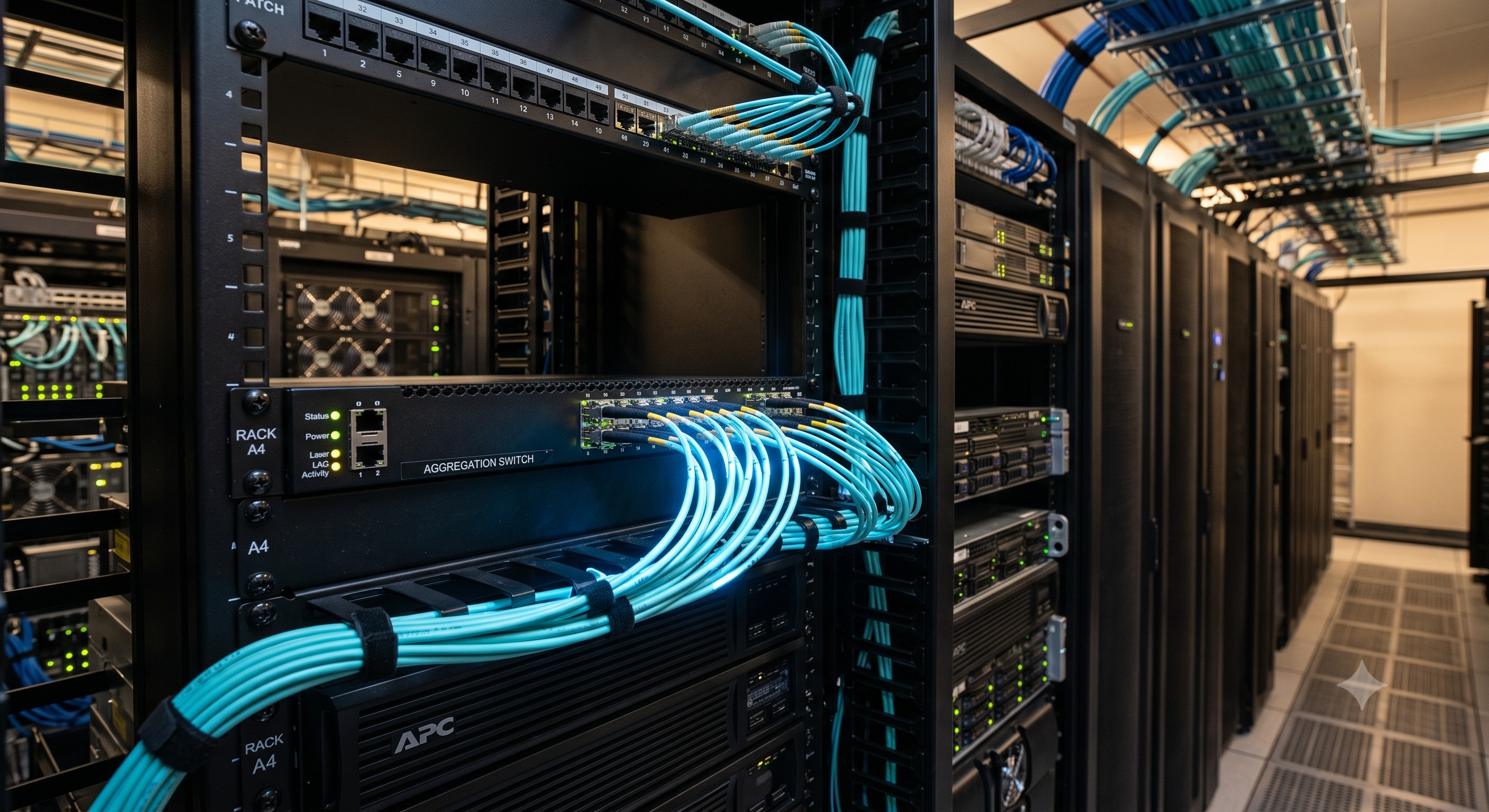
 Link Aggregation Network Switch Deep Dive: Internal ASIC Forwarding, Packet Pipelines, and Latency Limits
24 Jun, 2026. Posted by:XPONSHOP
Most Views Posts
Security Access FAQ: Configuring ACLs, Port Security & MAC Filtering on ONT Wi-Fi Network
2026-10-26 12:38:16
Merchant Silicon Throughput Processing Capacity FAQ: Expert Answers to Network Integration & Configuration Questions
2026-06-03 14:14:50
Troubleshooting ISP Edge Ethernet Switches: Optical Interfaces, Stacking Errors & L3 Protocols
2026-07-16 13:54:20
Popular Posts
Troubleshooting Nokia ONT: Optical Interfaces, Stacking Errors & L3 Protocols
2026-07-24 13:10:06
Security Access FAQ: Configuring ACLs, Port Security & MACsec on your Home ONT Wi-Fi Router
2026-08-10 11:08:41
OEM SFP Extreme Temperature FAQ: Expert Answers to Network Integration & Configuration Questions
2026-09-01 10:14:00
Managing OEM ONT: Initial Setup, Console Connection & Firmware Upgrades FAQ
2026-10-14 18:48:18
Random Posts
The Ultimate Guide to Brand Name vs. High-Quality Chinese OEM ONTs: Architecture, Backplane Bandwidth, and Deployment
2026-06-26 14:35:09
Which Default Passwords Are Used on Huawei S Series switches?
2025-10-22 09:02:34
Why Layer 3 Routing Hardware Outperforms Legacy Layer 3 Switches in Enterprise Core Routing
2026-05-22 15:54:41
The Ultimate Guide to optical switch wholesale China: Architecture, Backplane Bandwidth, and Deployment
2026-05-20 16:15:41
Troubleshooting XPON ONUs: Optical Interfaces, Stacking Errors & L3 Protocols
2026-08-14 11:20:57
Recent Posts
AI Optical Transceivers vs. Telecom Optical Transceivers: Two ‘Personalities’ of the Same Component
2026-10-30 11:30:33
Overcoming Network Bottlenecks: Enterprise Configuration Manual for Nintendo Switch NAT Type D Resolution
2026-10-30 10:06:06
Cisco Business 350 Series Managed Switch Physical Security and Power Efficiency - Official Technical Overview & Hardware Datasheet
2026-10-30 10:03:46
About
XponShop blog describes some basics for Huawei / ZTE /
Nokia / FiberHome GPON OLT, ONT, SFP, and Site Power...
such as configurations, issue troubleshooting, knowledge
sharing, and keeps updating.
Recent posts
 AI Optical Transceivers vs. Telecom Optical Transceivers: Two ‘Personalities’ of the Same Component
27 Mar, 2025
 Overcoming Network Bottlenecks: Enterprise Configuration Manual for Nintendo Switch NAT Type D Resolution
27 Mar, 2025
 Cisco Business 350 Series Managed Switch Physical Security and Power Efficiency - Official Technical Overview & Hardware Datasheet
27 Mar, 2025
AI Optical Transceivers vs. Telecom Optical Transceivers: Two ‘Personalities’ of the Same Component
27 Mar, 2025
Overcoming Network Bottlenecks: Enterprise Configuration Manual for Nintendo Switch NAT Type D Resolution
27 Mar, 2025
Cisco Business 350 Series Managed Switch Physical Security and Power Efficiency - Official Technical Overview & Hardware Datasheet
27 Mar, 2025
Products from the blog
Introduction: The Imperative of Intelligent Link Aggregation
In the modern enterprise and service provider landscape, bandwidth demands are growing at an exponential rate, driven by cloud computing, high-definition video streaming, and the proliferation of IoT devices. The humble network switch, once a simple bridge for data packets, has evolved into a sophisticated traffic management system. At the heart of this evolution lies the link aggregation network switch, a critical piece of infrastructure that combines multiple physical network links into a single, high-bandwidth logical link. This technology, governed by IEEE 802.3ad (now part of IEEE 802.1AX), provides not only increased throughput but also load balancing and link redundancy.
This deep dive explores the architecture, performance, and deployment of link aggregation switches, moving beyond basic concepts to examine the internal ASIC (Application-Specific Integrated Circuit) pipelines, packet forwarding mechanics, and the hardware engineering that makes line-rate performance possible. We will analyze how modern enterprise-grade switches handle the complexities of link aggregation, the crucial role of backplane bandwidth, and the latency limits that define a truly high-performance network.
Core Architecture & Switching Logic: The Silicon Backbone
The capabilities of a link aggregation network switch are fundamentally determined by its internal silicon architecture. Unlike commodity switches that rely on shared memory architectures, enterprise-class aggregation switches are built around high-performance ASICs designed for deterministic, line-rate forwarding. The evolution of these chips has been staggering; modern merchant silicon from vendors like Broadcom (Trident, Tomahawk series) or internally developed ASICs from major networking vendors now deliver switching capacities exceeding 12.8 Tbps and packet forwarding rates of over 4.2 billion packets per second (Bpps).
ASIC Pipeline and Packet Processing
The packet processing pipeline in a high-end link aggregation switch is a marvel of engineering. When a frame enters an ingress port, it immediately enters a hardware-based parsing stage. Here, the ASIC decodes the frame headers—typically up to 128 bytes deep—to identify key fields such as Source/Destination MAC, VLAN tags, and, crucially for aggregation, the hash keys used for load balancing. The forwarding decision is made in nanoseconds, a process known as cut-through or store-and-forward switching. Cut-through switching, which begins forwarding the frame before the entire packet is received, is paramount for achieving ultra-low latency, often measured in sub-microsecond figures (e.g., 450 nanoseconds for 10G Ethernet).
The internal logic for link aggregation (LAG) is typically implemented in hardware to ensure wire-speed performance. The switch ASIC utilizes a hashing algorithm (e.g., a 3-tuple or 5-tuple hash based on source/destination IP and port numbers) to distribute frames across the member links. This ensures that traffic from a single flow always uses the same physical link, preserving packet order. The latest generation of switches introduces flow-aware hashing that can dynamically adjust hash weights to avoid oversubscribing a single link, a feature critical for maintaining consistent performance in a leaf-spine topology.
Backplane Bandwidth and Fabric Architecture
A switch's backplane (or fabric) is the internal highway connecting all line cards and management modules. For a true link aggregation network switch, the fabric must be non-blocking, meaning it can handle the full aggregate throughput of all ports simultaneously. This is expressed as switching capacity. For instance, a 24-port 40G aggregation switch requires a fabric capacity of at least 960 Gbps to be non-blocking. Enterprise-grade chassis-based systems often employ a Clos fabric architecture, utilizing multiple fabric cards to provide resilience and massive throughput. The total switching capacity is a critical metric; a mid-range enterprise aggregation switch might offer 2.56 Tbps, while high-end core switches push well beyond 25 Tbps, ensuring that link aggregation groups of 100GE and 400GE interfaces can be fully utilized without contention.
Layer 2 vs. Layer 3 Aggregation Logic
While link aggregation is traditionally a Layer 2 (L2) technology, modern switches integrate it with Layer 3 (L3) routing capabilities. This is where the term 'Layer 3 switch' becomes relevant in the context of aggregation. The switch can perform IP routing on a LAG interface, allowing the aggregated link to act as a gateway to an entire subnet. This requires the hardware to also handle routing lookups in the ASIC pipeline, often integrating a TCAM (Ternary Content-Addressable Memory) for high-speed forwarding table lookups. The forwarding performance metric, measured in Mpps, accounts for both L2 switching and L3 routing. High-end models boast forwarding rates of over 1,440 Mpps, essential for campus backbones where inter-VLAN routing is a core function.
Technical Specifications
Evaluating a link aggregation network switch requires a technical analysis of its core specifications. The following table details the key performance indicators (KPIs) that network architects scrutinize when selecting an aggregation platform. These specifications directly correlate to the switch's ability to handle dense traffic loads, ensure low-latency transport, and support future network growth.
Beyond these headline figures, crucial design parameters include the maximum number of LAG groups (e.g., 512) and the maximum number of member ports per group (typically 8 or 16). Buffer allocation is another critical aspect; high-performance switches utilize dynamic buffer pools (e.g., 32 MB shared buffer) to absorb micro-bursts, a common phenomenon in storage and converged network traffic. The Mean Time Between Failures (MTBF) is a key reliability metric, with enterprise-class switches often exceeding 500,000 hours, reflecting their robust power supply and cooling system design. Compliance with RoHS (Restriction of Hazardous Substances) and industry standards like MEF (Metro Ethernet Forum) is also a necessary qualification for global deployment.
Deployment Scenarios: Maximizing Performance and Resilience
The practical application of link aggregation technology extends across various network environments, from enterprise data centers to carrier-grade edge networks. The following scenarios illustrate how the technical specifications translate into tangible network benefits.
High-Density Datacenter Aggregation (Leaf-Spine)
In a modern leaf-spine network architecture, the link aggregation network switch is the foundation of the aggregation layer. The spine switches, which provide high-speed connectivity between leaf switches, utilize link aggregation groups (LAGs) to connect to multiple leaf nodes. This creates a robust, multi-terabit fabric with deterministic latency. The switch's high forwarding rate (Mpps) ensures that traffic between thousands of servers is forwarded without degradation, while features like Priority Flow Control (PFC) and Enhanced Transmission Selection (ETS) from the IEEE 802.1Qbb standard enable lossless Ethernet for storage traffic (FCoE) and high-performance computing. The port density of 10/25/40/100 Gigabit Ethernet ports is a key selection criterion for scaling out the computing resources effectively within a limited rack footprint.
Campus Network Backbone with Redundancy
Link aggregation is indispensable in a campus core network. By aggregating multiple 10G or 40G links between the core and distribution switches, network architects can create a resilient backbone that supports thousands of users and high-bandwidth applications like 4K video conferencing. The active/active load-balancing nature of LAG (as opposed to STP blocking) doubles or quadruples the available bandwidth. The link aggregation switch plays a crucial role here, with support for multi-chassis link aggregation (MC-LAG or MLAG) being a significant differentiator. MC-LAG allows a single logical LAG to terminate on two separate physical switches, providing active/active redundancy at both the device and link level. This eliminates the topology limitations of spanning tree protocols and achieves sub-second failover times, which is critical for meeting strict SLAs.
Carrier-Grade Edge & MEF Compliance
For service providers, the link aggregation switch at the network edge must offer carrier-grade reliability and support for advanced features like Link Aggregation Group (LAG) for Ethernet Services as defined by MEF. These switches often incorporate dual hot-swappable power modules and fan trays, with 1+1 redundancy ensuring an uptime of 99.999% ('five nines'). The ability to support high port densities of 1G and 10G for subscriber aggregation, combined with hardware-based OAM (Operations, Administration, and Maintenance) capabilities like IEEE 802.1ag (Connectivity Fault Management), makes these switches ideal for delivery of Metro Ethernet and business internet services. The integration of sophisticated queuing and scheduling (e.g., 8 queues per port) enables granular QoS to enforce traffic policies and ensure service differentiation.
Conclusion: The Strategic Value of Intelligent Aggregation
The link aggregation network switch is far more than a simple port multiplier; it is a strategic component of a resilient and high-performance network infrastructure. As we've explored, the true power of these devices lies in their internal architecture—the high-speed ASICs, non-blocking fabrics, and sophisticated packet pipelines that enable line-rate forwarding and sub-microsecond latency. The quantifiable benefits are clear: increased aggregate bandwidth, network topology simplification through the elimination of STP, and link-level redundancy that ensures business continuity.
As network speeds continue to evolve toward 400GE and 800GE, the role of the aggregation switch will become even more critical. The choice of platform must be data-driven, with a focus on switching capacity (Tbps), forwarding performance (Mpps), and hardware redundancy (MTBF). By understanding these deep technical underpinnings, network engineers and IT leaders can make informed decisions that not only meet today's bandwidth demands but also provide a future-proof foundation for the next generation of digital transformation.